|
Re: Stewart's 1955 Packard 400
|
||||
|---|---|---|---|---|
|
Home away from home
|
I think I would be inclined to hold the head of the screw with a ‘Vice-Grip’ (or the backside if you have the room), and drill the head with ever increasing drill sizes, stopping at the tap drill size for the screw. At some point the screw head will be removable through shearing of the thin cylinder.
Posted on: 2021/8/9 23:47
|
|||
|
||||
|
Re: Ultrasonic Cleaner Rust removal
|
||||
|---|---|---|---|---|
|
Home away from home
|
I know this thread was about rust removal and ultra-sonic cleaners, but I have a tidbit of information about removing modern electro-plating.
The other day I was experimenting with stripping the electro plating off of modern nuts and bolts from the hardware store. My goal was to strip the plating off, and then use a Caswell black oxide product, with a penetrating oil sealer, to end-up with something that looked like a black phosphate finish. What I found was a Lysol 10X toilet bowl cleaner (hydrochloric acid) did a wonderful job of stripping the bright plating. Knowing that process had a chance of working, I started on the real job of ‘toning-down’ a set of sheet metal wing nuts for my ’48 battery hold down bolts. The modern wingnuts almost match the original design, but the bright plating on the new nuts was clearly too striking for the rest of the engine compartment, hence the desire to replicate a black phosphate finish. The Lysol product does a good job of striping the modern electro-plating. I guess the next question is whether Lysol toilet bowl cleaner will dispatch rust as well. dp
Posted on: 2021/8/9 23:33
|
|||
|
||||
|
Re: Various parts for sale
|
||||
|---|---|---|---|---|
|
Home away from home
|
Handykapp;
Carter data indicates that the 531 was intended for the 22/23 series 356 engine, and the 42-47 Super, while the 643 was intended for the 22/23 series 327 engine . . . so you’re looking for the ‘correct’ carburetor. The main circuit mixture appears to be slightly different between the 531S (richest), 643S (middle), and 531 SA (leanest). This mixture adjustment was done by which metering rod set was installed. The main jet size is identical among the three carburetors. I don’t consider the amount of diameter change in the various metering rods as being a big deal, in that all three are close to one another. The flange part number of the 531S & SA is different from the 643S, and the nominal idle mixture screw adjustment is different suggesting the potential of a porting difference in the flange. When I look at the individual pieces that would be used in the flange there seems to be the same start switch, throttle shafts and plates. The aluminum alloy cast parts are identical. Carter did not list the part number of the casting that contained the venturi. The sizes of all three venturi are identical between the carburetors in this discussion. I would consider the 643 and 531 similar enough to be a good starting point for any of the engines listed, but if available the 643 would be correct for a ’49 Super 8. dp
Posted on: 2021/8/1 23:35
|
|||
|
||||
|
Re: Electronic ignition
|
||||
|---|---|---|---|---|
|
Home away from home
|
Paul;
I found a close-up view of the way I mounted the kick-down circuit resistor. That circuit would be the green colored wires. The resistor is an Ohmite item with soldered connections. Again when you’re standing looking into the engine bay most of this stuff is hidden by the coil and ignition wires, and if your car is not equipped with an overdrive none of this is necessary. I forgot a few other subjects; first if you use a Pertronix coil, or any other aftermarket coil. Those items are likely without an integral mounting bracket. I know back in the day some coils used an integral coil bracket, while the others did not. If your car has a coil with an integral bracket, and you intend to use an aftermarket coil, then you will need to fabricate, or source, a hold-down bracket/strap. The good news is that ignition coil diameters have not changed in the last 80 years, and you don’t need to change the coil, but it is part of the ‘extra ignition voltage’ scheme. I made a hold down strap out of flat stock bent over a 1 ½ pipe coupling. The trick is to get the correct length . . . missing short is better than missing long. The other item is that Pertronix suggests the use of suppression type ignition wires. I’m not sure this applies to all of their product line, because the Model A does not have ignition wires . . . let alone suppression type wires. That car uses flat strips of a copper alloy (alloy and shape depends on the which year/month of manufacture), and they are surely not suppressed. The Model A has 15 years of ‘zero drama’ operation with electron ignition. I also used shiny black cotton covered stranded wire wires on my ’48 (those in the picture), but have subsequently changed to suppression type leads . . . nothing seemed to change when the wires were changed, so I’m not sure about the Pertronix guidance on suppression wires, and whether that guidance is for the entire product line. dp Attach file:  006A.JPG (292.64 KB) 006A.JPG (292.64 KB)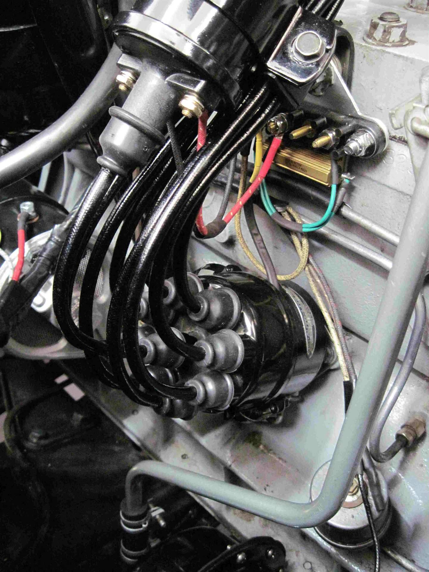
Posted on: 2021/7/25 20:27
|
|||
|
||||
|
Re: Electronic ignition
|
||||
|---|---|---|---|---|
|
Home away from home
|
Paul;
I’ve had success with both 12(-), and 6(+) Pertronix ignition systems. The local Model A expert that Ernie and I know is quick to caution about installing a Pertronix ignition module electrically close to an alternator. His advice is to connect the ignition module directly to the battery. I’ve been thinking about that advice for quite a while and the only thing I’ve come-up with is the potential of an AC component in the alternator output, especially if the internal capacitor is weak/fails, and I’m not real sure whether that type of failure is detectable without an oscilloscope. Readers should know that a Model A produces quite a bit of electro-magnetic interference from the secondary side of the ignition system, and the Pertronix system seems to be immune to this type of environment, but I suspect they conduct quite a bit of testing within EMI environments. The years of service using Pertronix ignition are; 15 years (12-), 8 years (6+), and 5 years (6+), with no known problems, or service needs. The local Model A expert also cautions about coil designs that place a resistor internally. His concern is the resistor will likely be at the bottom of the coil housing, and if the coil is oil filled the resistor may not be cooled if the coil is mounted ‘nose down’ . . . as in the Model A and ‘48-‘54 Packards. I use Pertronix epoxy filled coils that are just about in the middle of the recommended resistance range. Pertronix did say that reliability is a function of coil resistance (within the recommended range), but not enough to be concerned about. This business about coils has nothing to do with whether the ignition is electronic or points, and the guy that specializes in Model A sees a lot of failed parts and tries to spread the word when he runs across a problem. Pertronix’s recommendation on how to implement the functionality of the overdrive kick-down feature in one of their 6+ units is in the attached file. Seems the 7 ohm circuit will defeat the spark sufficiently, while also limiting the current through the ignition module. Without the resistor the kick-down circuit would essentially ‘short to ground’ the ignition module for whatever the latent time is to have the overdrive solenoid change position. I suspect, but don’t know by how much, that the ignition module’s reliability would suffer with the module shorted to ground. Paul I think you can install an electronic ignition with a good amount of stealth, however on an Autolite system the Pertronics wires will enter the distributor versus the external connection on the OEM unit. My goal was to install the Pertronics system without altering the stock wire loom, so I mounted a barrier strip to make all of the connections (within reach of the stock loom), and mount the 7 ohm resistor. All of that mess was mounted to the side of the cylinder head hiding under the coil and ignition wires. I agree with Mechagon, the conversion is straightforward, and is not glaring even if you include the constraint of ‘do no harm’. HH56 comment about having almost ‘no room for error’ with a 6 volt starting system is equally correct. I have a NAPA 3EH battery, and soldered AWG 00 cables in my ’48 288, and that combination is acceptable. There are no substitutes for cold cranking amps and circular mils. Paul it’s up to you . . . its 100% reversible if you decide to restore the car to ‘as built’ condition. dp
Posted on: 2021/7/25 19:01
|
|||
|
||||
 pertronix6VPGInstallationInstructions_withOverDrive.pdf
|
Re: 1940 120 rear axel bearing service
|
||||
|---|---|---|---|---|
|
Home away from home
|
Bill;
A while back kevinpackard was embarking on the task of repacking the rear bearings on his car. I provided him a supplement to the shop manual that I’ve been working on and off for some time now. The specific posting is in the project blog section under KPack’s 1954 Panama, page 64, posting #634. See the following link; Re: KPack's 1954 Panama [Project Blogs] - Packard Motor Car Information (packardinfo.com) Additions to the supplement that were identified during Kevin’s project were: 1. A note to lubricate the inner seal with gear oil, especially if a new seal is being installed. 2. A note to lubricate the outer seal with either gear oil or bearing grease, especially if a new seal is being installed. 3. A note on the addition of a series of center punch marks if a loose fit is encountered between the outer bearing race and the axle housing bore. There was a discussion on all of those subjects as the blog proceeded. I know the supplement was written for the '48-'54 automobiles, but I believe the design of the '40 is quite similar. The hardest part of that job is the removal of the brake drums . . . after that it is pretty much routine. dp
Posted on: 2021/6/29 19:08
|
|||
|
||||
|
Re: Packard Engine to GM Auto Transmission Adapters
|
||||
|---|---|---|---|---|
|
Home away from home
|
Let’s shoot a flare towards Speedwell USA, and have Ross weigh-in on the bolt torque.
dp
Posted on: 2021/6/15 23:50
|
|||
|
||||
|
Re: Packard Engine to GM Auto Transmission Adapters
|
||||
|---|---|---|---|---|
|
Home away from home
|
If it was a standard shift flywheel the bolts are torqued to 55 - 60 ftlbs . . . that would be for a 7/16 X 20 thread diameter and pitch.
I looked in the Ultramatic section of the shop manual and came up empty. Assuming the crank shaft is the same Ultramatic v Standard we can assume the crank is good to 60 ftlbs. Now the question is what grade bolts did you buy? Another question would be how much of a lubricant is Loctite ? dp
Posted on: 2021/6/15 23:28
|
|||
|
||||
|
Re: Packard Engine to GM Auto Transmission Adapters
|
||||
|---|---|---|---|---|
|
Home away from home
|
John a while back (post # 10) you reported the flywheel bolts were torqued to 25 ftlbs with blue Loctite. The torque sounds low to me, was that a typo, or is that the torque specified for that flex-plate?
dp
Posted on: 2021/6/15 22:04
|
|||
|
||||
|
Re: timing a 1949 deluxe 288
|
||||
|---|---|---|---|---|
|
Home away from home
|
Bear:
Ross Miller’s video on the subject has a pretty clear view of the clamp @ 11:10. https://www.youtube.com/watch?v=XiYY11rwjQ6A&t=1227s or search Installing a Distributor | Packard Straight 8 | Ross Miller | Speedwell Garage - YouTube The clamping screw is at six o’clock on the clamp. The intent is to tighten the bolts at 3 & 9 o’clock before the distributor is installed, and then with the horizontal screw loose install the distributor. Timing is then conducted statically or dynamically with a timing light, following which the clamping screw is tightened. On the left side of the clamp is a feature that allows the gauging of small changes to the timing without the use of a timing light. To do this the clamp bolts at 3 & 9 o’clock are loosened just enough to rotate the body of the distributor. The scale on the left indicates the new datum, or bias to the initial adjustment done with the timing light. I’ve been told that such a feature allowed for a timing adjustment to accommodate a low octane fuel. Once the distributor is adjusted the clamp hold down bolts are re-torqued, and if the owner thought that the poor fuel quality situation had passed the distributor timing bias could be returned to the original position. At least that’s the story that was told to me . . . who knows, it could be true. Once you have the distributor out you can remove the bolts, I believe the bolts have a shoulders, and inspect the mechanism. I believe you will find the clamp has limited authority on timing adjustments, and should be installed initially at zero bias. dp
Posted on: 2021/5/30 23:25
|
|||
|
||||


.jpg")


