|
Re: Another remote master cylinder reservior
|
||||
|---|---|---|---|---|
|
Home away from home
|
Sorry Steve the first production run of 10,000 have been spoken for . . .!
 Howard this is a ‘homebrew’, except for the reservoir and ‘P’ clamp. This design started at the 3-inch hole in the battery tray, and grew from there. An aluminum ‘top hat’ fits into the 3-inch hole from the battery side, and is capped with an aluminum cup. Once the center bolt that holds the ‘P’ clamp is torqued the ‘hat and cup’ pinch the battery tray and the whole mess locks-up quite nicely. There is also one other bolt that does double duty. First it provides sufficient pinch to keep the hat and cup from rotating, and second the bolt inhibits the ‘P’ clamp from rotating downward in the event the central bolt loosens. Photo_1 shows the aluminum ‘top hat’ and ‘cup’. This photo was taken before the second bolt hole was drilled, but it is located essentially at the radius where the ‘P’ clamp is bent to begin the circular portion of the clamp. Photo_2 shows the reservoir mounted on the battery box. The box was removed for a ‘paint-job’, otherwise the reservoir could be installed with the battery box already installed in the car. Photo_3 in the first posting shows the final installation. Parts Used: The Mico reservoir and remote cap were purchased from Capital Clutch & Brake, West Sacramento, CA, contact ‘ccbvinnie@aol.com for details. The cap and reservoir have same thread geometry as Packard master cylinder. Mico Cap 30-030-031 Drilled and tapped 1/8 pipe Mico Reservior 20-920-009 Outlet drilled and tapped 1/8 pipe Expect a lengthy wait for the Mico parts. You provide the tubing fittings that thread into the 1/8 NPT. McMaster-Carr EPDM ¼ ID, ½ OD tubing EPDM is compatible with glycol and silicone based brake fluids. e-Bay Two pieces of 4.25 X 1 aluminum round stock. Minutia: The EPDM tubing is provided abrasion protection with split ½ inch plastic loom, with an outer heat shrink cover. Those details are visible in the photo in the first posting. The intent is; if a leak in the EPDM occurs the fluid will be routed away from the under-hood painted surfaces and exit at the master cylinder. However, I have no intention to test this feature. The ‘P’ clamp is not painted, but was treated with Caswell cold black oxide resurfacing concentrate, with penetrating oil protective coating . . . essentially ‘gun bluing’. The electro-plating applied by Mico was stripped with Lysol toilet bowl cleaner, which works quite well. The aluminum cap was masked where the ‘P’ clamp contacts it, so except for the area where the pinch occurs with the battery tray there is no paint at the interfaces. In the event of the central bolt loosens the anti-rotation pin should inhibit rotation of the reservoir, and the driver’s side air duct keeps the reservoir from exiting straight-down. After the unit was installed I believe the hose alone will keep the reservoir from rotating, so the business of an anti-rotation bolt might be a concept only. Since the ’51-’54 battery tray has enough room to hold two six volt Optima batteries I carry an extra as a back-up . . . just in case. I might be the only six volt car at the Saturday night car show, so getting a ‘jump’ from that crowd might be a challenge. The battery cables were made to reach either battery, so ‘swapping’ batteries involves only ‘swapping’ cables. The hold-down was fabricated from standard band stock purchased from Home Depot. A simple outer cover tries to hide the Optima ‘six-pack’ look, and pretend the car is equipped with a Willard unit. When I was installing this stuff I was reminded, again, on how infrequently I check the master cylinder fluid level . . . it was on the low side. It took a while for the bubbles to subside as the fluid transferred from the upper reservoir to the master cylinder, but the bubbles finally stopped and the level stabilized. That alone is enough evidence to suggest that everything below the new reservoir was leak free, that is, if an air leak existed, say at the master cylinder cover plate, then the fluid level would have gone down without a lot of air bubbles coming to the surface. My first plan was to fabricate this mount out of sheet stock welded into the basic shape of the hat and cup, but my welding skills haven’t been refined to a point there that was a viable option. Attach file:  Photo_2.JPG (233.43 KB) Photo_2.JPG (233.43 KB)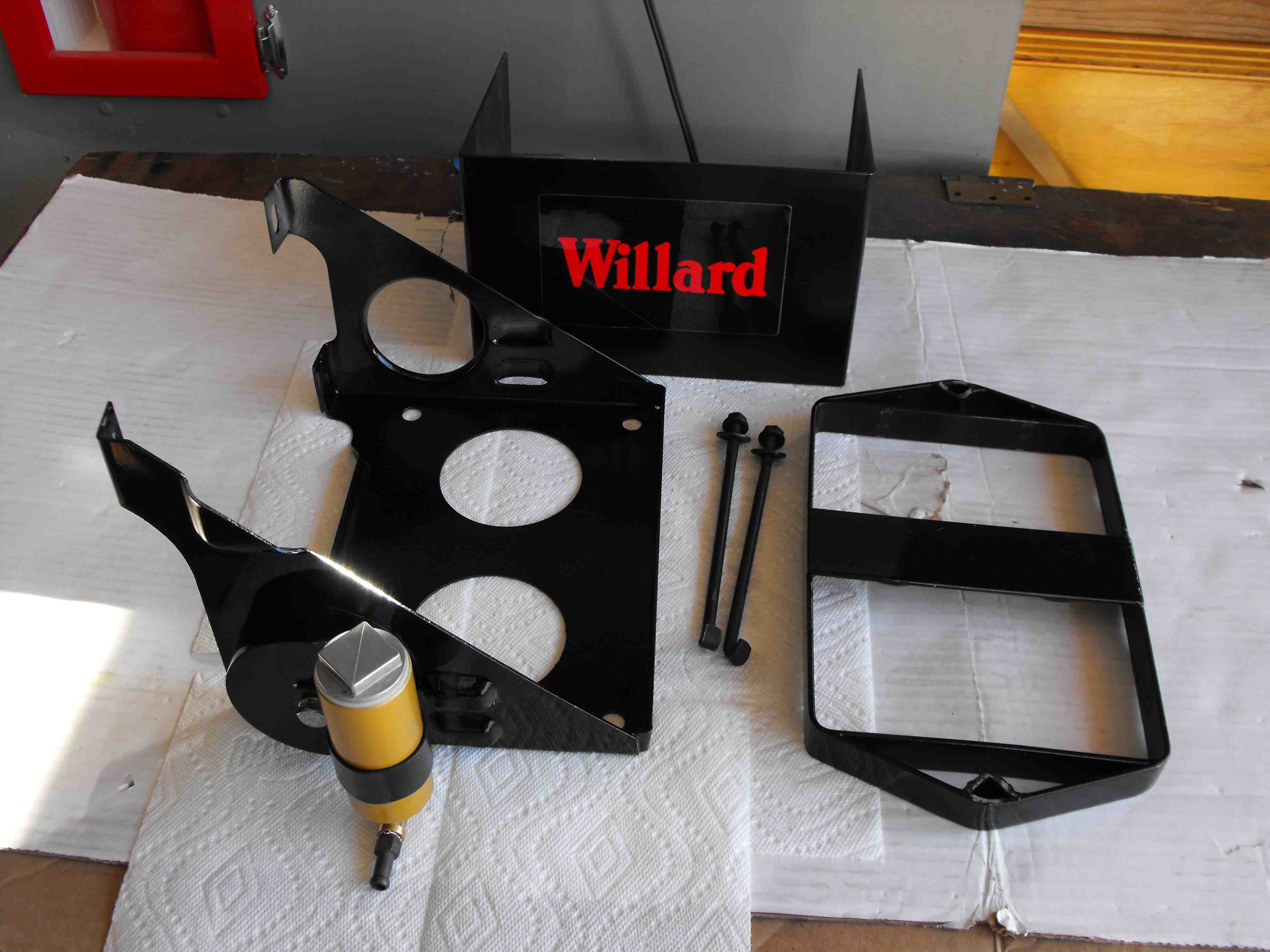 Photo_1.JPG (151.15 KB) Photo_1.JPG (151.15 KB)
Posted on: 2021/11/28 13:44
|
|||
|
||||
|
Another remote master cylinder reservior
|
||||
|---|---|---|---|---|
|
Home away from home
|
I finally installed one on my '54. It's another "drill no holes" design.
dp Attach file: Photo_3.JPG (281.30 KB)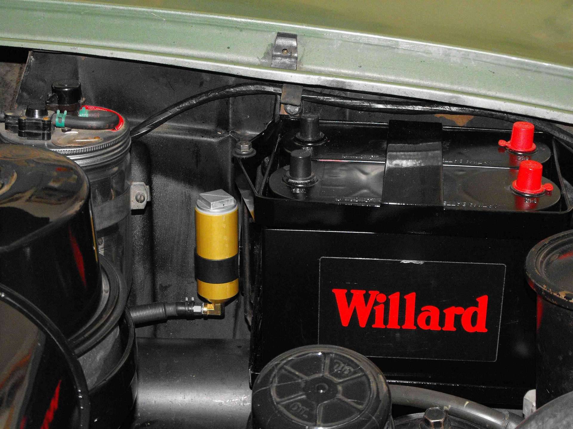
Posted on: 2021/11/27 21:03
|
|||
|
||||
|
Re: Transmission and overdrive oil
|
||||
|---|---|---|---|---|
|
Home away from home
|
Packardwagon; The quick answer is: mineral gear oil, known as GL-1, but which weight has a bit of a back story.
In the website’s Literature Archive, you will find a User’s Manual for your car, and within there will be a lubrication chart that contains call-outs on the various lubrication specifics. Over the years you should also note that both 90 and 140 weight oil is recommended. In the 1942 Clipper manual there is additional insight that 140 weight is associated with warm weather, 90 weight for cold weather, and 80 weight for extremely cold weather . . . however in the very next sentence following the viscosity recommendation’s is a statement that the transmission oil should be drained and refilled once a year, preferably in the Spring. Later manuals make no mention of the 140-weight oil, but do mention switching to 80W only if difficulties in shifting are encountered. I personally use 90W GL-1 in the transmission and overdrive year-round. dp
Posted on: 2021/11/26 13:40
|
|||
|
||||
|
Re: BigKev
|
||||
|---|---|---|---|---|
|
Home away from home
|
I do apologize . . . my ’54 was off-site, and I couldn’t photograph until today. Seems like you’ve completed the driver’s side already, so this is pretty much academic at this point.
With respect to the door weather strip ‘flap’, I believe you’re correct in placing the rubber ‘on top’ of the screw. Based on your photo in post #2467 versus my attached photo, along with Jerome’s, the OEM seal may have started with a slightly different cross section in that area, but then again I’m looking at a seal that has had a good number of years of ‘forming’ pressure. Attach file: WeatherSeal002.jpg (217.13 KB)
Posted on: 2021/10/23 18:11
|
|||
|
||||
|
Re: 51 Packard 250 Headlights are dim
|
||||
|---|---|---|---|---|
|
Home away from home
|
51Pack;
I would also start with ensuring the head light grounds are in good shape as HH56 mentioned, and then a quick check of the system voltage at the battery posts as Ross suggested . . . finally measuring the voltage at the terminal block would be worthwhile. If anything looks ‘crusty’ then disassemble, clean, and re-assemble . . . ultimately the terminals must be electrically clean, which starts with being physically clean. While not plagued with ‘dull’ head lights, I did wire my ’48 headlights with a system quite similar to the circuit HH56 posted. The only exception was the use of two circuit breakers, with separated feeds to the #30 pole of the relays. The original problem was degradation of the headlight switch circuit breaker which resulted in me driving down the road with the lights coming on, followed by the lights going off, and then coming back on again . . . not good driving at night with no headlights. The OEM breaker was replaced prior to building the relay system, but I must admit I changed the toe switch, as Tim Cole suggested for good measure. Since I didn’t want to install another system that had the same single point of failure as the OEM circuit, my modification was to ‘double-up’ on the circuit breakers. If something runs amiss my bet is it won’t happen to both circuits at the same time, and I can ‘limp’ home . . . with some amount of lighting. The circuit breakers are 30A, which is just about twice the current needed for the head lights (that’s quite normal for the circuit breaker to be twice the running load). The OEM breaker is mounted under the dash, and is therefore subject to temperature pretty much the same as the driver & passengers. The new under hood circuit breakers are subject to temperatures quite a bit higher. There will be a degradation of the ’trip current’ at the higher thermal environment, so the 30A rating might not be absolutely correct at the higher temperatures, and if the components are operating at typical thermostat settings the maximum current rating could be 50% of the rated value. Just be mindful of where the relays are mounted if you decide to install relays. Mine are located on the inner fender, just about the same location that HH56 selected. In my ’48 they’re mounted above the battery where the OEM wiring harness is routed . . . . that would be just aft of the OEM terminal strip, which also minimizes the total length of wire. The attached file has further explanation. By the way Halogen lights come in several different wattages, with some matching the OEM load rating (that’s a good thing). If the lights you installed have a larger wattage rating than the original head lights, then I would recommend a relay system . . . before the OEM light switch lets you down. dp
Posted on: 2021/10/5 22:31
|
|||
|
||||
 HeadLightRelay002.pdf
|
Re: 1940 Turn Signal Wiring Diagram
|
||||
|---|---|---|---|---|
|
Home away from home
|
I forgot to add a sentence about front parking lights . . . if the car never had turn signals from the factory the front lights are not likely dual filament, therefore they need to be managed much like the stop lights. That is the turn signal shares a single filament with another function. Gar your wire count might be as high as 8 to cover the front bulbs. If we call the parking input power as circuit 8, then 8 & 4, and 8 & 5 will be common with the signal switch centered. With the switch in the right turn position then 2 & 4 are common, and 8 & 5 remain common.
Posted on: 2021/10/3 19:03
|
|||
|
||||
|
Re: 1940 Turn Signal Wiring Diagram
|
||||
|---|---|---|---|---|
|
Home away from home
|
Gar;
Because the pilot lamp is mounted inside the flasher housing, you should have 7 wires there. They are: 1. Stop light power input 2. Flasher power input In the photo looks like either the Red or Black wires 3. Flasher pilot lamp input In the photo looks like either the Red or Black wires 4. Right front lamp output 5. Left front lamp output 6. Right rear lamp output 7. Left rear lamp output The remaining brown wire in the 3 prong flasher socket should be perhaps hot always, or hot with ignition key on. Assuming you find power at the brown prong I would jumper power to the black prong. Stick a fuse in the jumper just in-case. If the indicating lamps turn ON then the black wire is the pilot lamp input, however if the lamps do not come on then place the turn signal switch into a ‘turning’ position and retry jumping brown to black. Assuming the lamps are good then one of the lamps should light, and you just confirmed the black wire is the pilot input. If this fails then you will have to repeat the process with the red wire, but I’m expecting the black to be the pilot and the red the load side of the flasher, that is, the flasher power input into the flasher switch. The next step is to find the brake light circuit. One of the wires should be hot only when the brakes are applied. You can trace the circuit from the brake light switch to the turn signal switch. Since wire 1 & 6, and 1 & 7 are common finding the brake light input power wire is best done by tracing the wire itself. The only wires left are going to the 4 corners of the car. One at a time we want to apply power and confirm which light is ON. Did I mention you’re writing all of this down, because once you’ve identified all 7 wires that’s your homemade wiring diagram. See thread ‘1956 Clipper Turn Signal’ posting #6. The attached diagram is for the Packard turn signal switch (it should be electrically identical to yours), but because the pilot lamps are dash mounted the Packard switch is a 6 wire design. dp
Posted on: 2021/10/3 17:36
|
|||
|
||||
|
Re: coil on plug
|
||||
|---|---|---|---|---|
|
Home away from home
|
A low tension ignition system was developed for piston power aircraft years ago. See article
https://www.aircraftsystemstech.com/p/low-tensionmagneto-system-high-tension.html The only parts we don't have access to are the 'brushed' distributor cap, and a low tension coil. Typically low tension systems are only needed at high altitude . . . not sea level, so not sure there would be an automotive application to forage for parts. dp
Posted on: 2021/10/1 12:10
|
|||
|
||||
|
Re: 1956 Clipper Turn signal flasher
|
||||
|---|---|---|---|---|
|
Home away from home
|
Howard; I think the diagram is OK.
Assuming the pilot and load are synchronized, then let’s put the right turn signal ON and analyze the circuit when the Orange wire is ‘hot’. Both the Orange and Pink are ‘hot’ resulting in zero voltage drop across the left indicator . . . that is when the right turn signal is ON, the left indicator is not producing light. That seems correct so far. With the Pink wire still ‘hot’ the right indicator will be powered, and have a ground path through the Left turn signal bulb. Since incandescent bulbs have less resistance when cold this ground path is sufficient to provide enough voltage drop across the right indicator to produce light. Seems that’s correct also. dp
Posted on: 2021/9/23 14:10
|
|||
|
||||
|
Re: trunk upholstery kit
|
||||
|---|---|---|---|---|
|
Home away from home
|
JWL’s information is consistent with the perception/assumption that the senior car trunks were finished with up-graded materials, that is, carpet v. rubber mat. I must admit my rubber mat assumption may have been a figment of my imagination knowing the ’48 Eight front mat material and GM’s use of rubber mats a few years later in their ‘lesser’ product lines. By the time I bought my ’48 Deluxe the trunk had been media blasted, repainted low gloss black, and dark gray/black thin trunk carpeting glued in . . . over every surface, save the spare wheel well. I’m not sure that I’ve ever seen original 22-23 series trunk finishes. The only ‘stuff’ left in my ’54 trunk was the three piece ‘tar paper’ first layer for the flat surface, two ‘ropes’, a flattened jack box playing the role of a trunk mat, and a lot of flocking lying about.
I guess bear should follow bkazmer’s advice of flocking the surfaces that are not the ‘floor’, and HH56’s advice on a center mat. I know when I looked real close to the flocking on my ’54 the material was not a single color, more of a blend, but I’m not sure if ’48 flocking was a single color material. I bet after a few years the color of the adhesive was obvious. If flocking is not on the horizon the finish should present with almost no ‘shine’, quite subdued. From the parts catalog there’s an impression that the trunk color did not vary with paint code . . . other than the incidental over spray, so the flocking and mat may have been from the same family, but not necessarily matching colors. Given the color of my fender ‘ropes’, and the flock residue the ’54 trunk finishes likely presented with a brown/tan hue in that time period, which is quite consistent with HH56’s information that ’51 cars had the same color presentation. The observation made by bkazmer is the ’48 – ’50 cars likely presented as a gray hue. Bear, if you jump to page 44 in KPack’s 1954 Panama project blog you will see various ‘non-OEM’ trunk presentations. My experience is the in-door / out-door carpet from Home Depot would need a lot of help to bend around tight radii, and if you were successful, outside bends would expose a ‘different’ texture. Thinner non-pile material does not have that restriction. Another project blog to look at is Joe’s ’49 Club Sedan around page 8, where Joe shared his idea/method to add upholstery elements to the trunk lid. I shamelessly stole that one, but did not back the material and just glued the magnets to the carpet and allowed the fabric fit the curved contour of the lid. I also use magnets to hold the fender upholstery . . . very little glue. I think the bottom line is that your quest to find a truck refinishing kit may not be successful, but you can get real close to OEM standards by buying the materials individually, but you can equally go crazy back there.
Posted on: 2021/9/19 14:01
|
|||
|
||||


