|
Re: V8 Engine Disassembly, Inspection
|
||||
|---|---|---|---|---|
|
Home away from home
|
The puller screw has to rest against the end of the crankshaft. The factory puller has a conical end which goes in the bolt hole and self centers. If you use washers, just make sure they aren't too big.
Attach file:  K-M-J-5992.jpg (207.46 KB) K-M-J-5992.jpg (207.46 KB)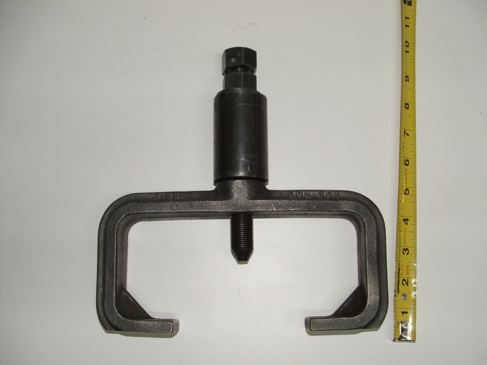
Posted on: 3/26 14:04
|
|||
|
||||
|
Re: Stewart's 1955 Packard 400
|
||||
|---|---|---|---|---|
|
Home away from home
|
Ross is correct about moving the carpet forward. The rear notch which you have against the rear footrest in the picture should be against the front of the front seat frame.
Posted on: 3/21 11:31
|
|||
|
||||
|
Re: V8 Engine Disassembly, Inspection
|
||||
|---|---|---|---|---|
|
Home away from home
|
If you don't have access to the J-5992 vibration damper remover, there is an interesting alternative solution shown in this YouTube video.
Home made vibration damper puller
Posted on: 3/15 17:47
|
|||
|
||||
|
Re: Auto City Classics 1951-1956 Packard OE Finish Steel Gas Tank TS5156PKQ
|
||||
|---|---|---|---|---|
|
Home away from home
|
I put one in my 56. The only issue I had was with the installation. I had to bend the filler neck to make it accessible through the filler door. I have had no problems with the tank since installing it.
Posted on: 3/15 12:24
|
|||
|
||||
|
Re: Torsion Levelling
|
||||
|---|---|---|---|---|
|
Home away from home
|
All of your pictures are giving not found errors, so this is based on the text.
I assume that your pictures include the compensator you installed and the compensator control/delay switch. I hope you can get them to load so we can see. What is the time of the porpoise cycle? Is there a delay between cycles or is it constant? The compensator control/delay switch is supposed to provide about a seven second delay to allow for changing conditions. The 56 compensator gear box has limit switches in it and if it is going all the way up and down, they would seem to be working. The 55 compensator has external limit switches. How did you wire your limit switches? Does the car have the manual level switch under the dash? What happens when the car is parked, does it sit with the front down/rear up, does it level, or does it porpoise? It sounds like it is not able to identify level. That is a function of the compensator control/delay switch. Pictures and more information will help.
Posted on: 2/27 2:39
|
|||
|
||||
|
Re: Weird Surging
|
||||
|---|---|---|---|---|
|
Home away from home
|
Sounds like it is time to hook up a gauge to the DirectDrive port and watch the pressure. Also hook up a tachometer as bullish—ter suggested. If you don’t have someone to monitor and record the pressure, rpm, speed and surge, setup a video camera to record the test and look at the data after.
Posted on: 2/23 2:31
|
|||
|
||||
|
Re: !955 400- Bleeding the brakes
|
||||
|---|---|---|---|---|
|
Home away from home
|
There is nothing special to it.
I replaced every component of the hydraulics, hooked up a power bleeder and the system bled like any other.
Posted on: 2/16 11:03
|
|||
|
||||
|
Re: Torsion level suspension
|
||||
|---|---|---|---|---|
|
Home away from home
|
It needs a few things to go from prototype to production.
To support 55s, I need to change the current sensor, add two isolators, and make an adaptor cable. I'm thinking of changing the timer to be more accurate by changing from a 555 to a crystal. I need to make more complete documentation. I'll keep you posted.
Posted on: 1/6 18:49
|
|||
|
||||
|
Re: Torsion level suspension
|
||||
|---|---|---|---|---|
|
Home away from home
|
Howard,
I built the test box. The last time I replaced a Compensator Control/Delay Switch, I bench tested it manually. I was glad I did as I found a stuck relay which I fixed prior to installation. Last year I was driving a friend's Clipper and identified an approximately 0 second delay. He got a NOS Compensator Control/Delay Switch which I suggested be tested before installation. This got me thinking that there should be a better way to test it. So I decided to build one. It started as a tester for the Compensator Control/Delay Switch out of the car and I kept adding functions.
Posted on: 1/4 16:52
|
|||
|
||||
|
Re: Torsion level suspension
|
||||
|---|---|---|---|---|
|
Home away from home
|
Here is a quick description of the features, functions, and tests of the test box:
Torsion Level Test Box Switches and indicators: Up and Down arrow indicators: Lights when the Compensator Control/Delay Switch engages one of the direction relays and the contacts successfully close sending a signal to the limit switch. Limit indicator: Lights when the direction relay is sending a signal to the Limit switch and the Limit switch is not sending the signal to the solenoid switch. Motor indicator: Lights when the solenoid switch is closed and sending a power to the Compensator motor. Delay display: Displays the number of seconds the Compensator Control/Delay Switch has delayed engaging the direction relay. The delay count begins when the Compensator Control/Delay Switch contacts close and current is drawn and ends when the direction relay contacts close. The Delay display works for Out of car Mode tests and for Automatic IN car Mode tests Power indicator: Lights when the test box power is switched on and the test box has power. Reset button: Resets the Delay display counter to zero. Brake indicator: Lights to indicate that the brake light switch has interrupted the power to the Compensator Control/Delay Switch. This indicator also lights when the torsion level manual switch is turned off and when the manual level control switch is operated. Power switch: Turns the power to the text box on and off. Mode switch: Switched between out of car testing of the Compensator Control/Delay Switch and in case testing of all of the suspension components. Up/Down switch: Signals the solenoid switches to run the Compensator Up or Down. This switch only operates in In Car Mode with the Man/Auto switch set to Manual. Bypass/Limit switch: Routes the Up/Down switch signals to the solenoid switched either with or without the use of the limit switches. Amps display: Shows the total current in use by the torsion level control circuits. This includes the delay, direction relay and solenoid switch. Man/Auto switch: Selects between the Compensator Control/Delay Switch and the manual Up/Down switch for signaling the solenoid switches to operate the compensator. Connections: 1. 12 volt DC power supply to run the test box. Clips to attach to a source in the car. 2. Connects to all the connectors in the 56 Compensator Control/Delay Switch. All of the harness connectors connect to the test cable. 3. Ground clip for the Compensator Control/Delay Switch 3. Clips to attach to the solenoid switch outputs Tests: Two test modes: 1. Out of car: tests the Compensator Control/Delay Switch 2. In car: Tests the Compensator Control/Delay Switch, limit switches, solenoid switches, and compensator motor. Out of car tests: Connect the test box: 1. Connect the test cable Green, Yellow, and Pink wires with the male bullet connectors to the Compensator Control/Delay Switch 2. Connect the black ground clip to the Compensator Control/Delay Switch 3. Connect the test box to a 12 volt DC source using the Red and Black clips Test the Compensator Control/Delay Switch out of the car: 1. Turn on the test box. 2. Set the MODE switch to OUT. 3. Move the Compensator Control/Delay Switch lever to one side. If the delay timer contacts and heating element work, the ammeter will display the current drawn by the timer and the delay display will show the delay time in seconds. If the delay timer completes the delay, it will engage the compensator direction relay. If the relay coil works, the ammeter will show an increased current draw. If the compensator direction relay works, you will hear it “click” and the direction indicator will light. Otherwise the ammeter will show the increased current value and the delay display will continue to count delay seconds Otherwise the ammeter will remain the same and the delay display will continue to count delay seconds. Otherwise the ammeter will remain the same and the delay display will continue to count delay seconds. Otherwise the ammeter and delay display will show 0. 4. To test the other direction, move the Compensator Control/Delay Switch lever to the neutral position, reset the delay display with the RESET button and move the Compensator Control/Delay Switch lever to the other side. In car tests: Connect the test box: 1. Connect the test cable Green, Yellow, and Pink wires with the male bullet connectors to the Compensator Control/Delay Switch. 2. Connect the wiring harness Green, Yellow, and Pink wires with the male bullet connectors to the test cable Green, Yellow, and Pink wires with the female bullet connectors. 3. Connect the wiring harness Orange wire and the Up limit switch Orange wire to the test cable Orange wire. 4. Connect the wiring harness Blue wire and the Down limit switch Blue wire to the test cable Blue wire. 5. Connect the black ground clip to the Compensator Control/Delay Switch 6. Connect the clips on the test box Red and Brown wires to the solenoid switches Red and Brown wire connections. 7. Connect the test box to a 12 volt DC source using the Red and Black clips To test the Fuse, Brake Light Switch, Torsion Level On/Off Switch, and the optional Manual Level Switch (For each of these tests we assume that the other three functions are working): 1. Turn on the test box. 2. Set the MODE switch to IN. 3. Fuse test: If the Brake light is lit, there is no power to the Compensator Control/Delay Switch Green wire and the fuse is bad. 4. Brake Light Switch test: Press the brake pedal If the Brake Light Switch works, the Brake light will light. 5. Torsion Level On/Off Switch test: Turn the Torsion Level On/Off Switch Off If the switch works, the Brake light will light. Turn the Torsion Level On/Off Switch On If the switch works, the Brake light will go out. 6. Manual Level Switch test Move the Manual Level Switch to the lower position. If the Manual Level Switch works, the Brake light will light. Move the Manual Level Switch to the raise position. If the Manual Level Switch works, the Brake light will light. Test the Compensator Control/Delay Switch in the car: 1. Turn on the test box. 2. Set the MODE switch to IN. 3. Set the AUTO/MAN switch to AUTO 4. Load or unload the car so it is not level. If the delay timer contacts and heating element work, the ammeter will display the current drawn by the timer and the delay display will show the delay time in seconds. If the delay timer completes the delay, it will engage the compensator direction relay. If the relay coil works, the ammeter will show an increased current draw. If the compensator direction relay works, you will hear it “click” and the direction indicator will light. Otherwise the ammeter will show the increased current value and the delay display will continue to count delay seconds Otherwise the ammeter will remain the same and the delay display will continue to count delay seconds. Otherwise the ammeter will remain the same and the delay display will continue to count delay seconds. Otherwise the ammeter and delay display will show 0. 5. To test the other direction, move the Compensator Control/Delay Switch lever to the neutral position, reset the delay display with the RESET button and move the Compensator Control/Delay Switch lever to the other side. Test the complete suspension under the control of the Compensator Control/Delay Switch: 1. Execute the Compensator Control/Delay Switch in the car test. 2. From the successful completion of the four tests in step 4: If the Solenoid switch coil works, the ammeter will show an increased current draw. If the solenoid switch works, you will hear it “click” and the motor indicator will light for the direction. If the leveling motor works, it will run. If the leveling mechanicals work, the car will level. If the car reaches the limit for travel in that direction, the Limit Switch will disable the solenoid switch, the motor will stop, the Motor light will go out, and the Limit light will light. Otherwise If the car reaches the level position, the Compensator Control/Delay Switch contacts will disengage, the delay will disengage, the direction relay will disengage, the solenoid switch will disengage, the motor will stop, the direction and motor lights will go out and the ammeter will go to zero. The Delay display will show the delay time until the RESET button is pressed. Otherwise it the Compensator continues to run without reaching level or the limit in that direction, damage may occur. Otherwise the Compensator will work against the mechanical problem and damage may occur. Check the Compensator gear box and links. Otherwise the Compensator motor will not run. Check the Compensator motor. Otherwise nothing will happen. The coil energizes, but the contacts do not engage. Check the Solenoid switch. Otherwise nothing will happen. The coil does not energize. Check the Solenoid switch Test the suspension manually without the Compensator Control/Delay Switch: 1. Turn on the test box. 2. Set the MODE switch to IN. 3. Set the AUTO/MAN switch to MAN 4. To include the Limit switches in the test set the BYPASS/LIMIT switch to LIMIT 5. To raise the car press UP on the UP/DOWN switch The UP light will light Continue from step 2 of “Test the complete suspension under the control of the Compensator Control/Delay Switch:” 6. To lower the car press DOWN on the UP/DOWN switch 7. To exclude the Limit switches from the test set the BYPASS/LIMIT switch to BYPASS The UP light will light Continue from step 2 of “Test the complete suspension under the control of the Compensator Control/Delay Switch:” 8. To exclude the Limit switches in the test set the BYPASS/LIMIT switch to BYPASS WARNING: CARE MUST BE TAKEN WHEN OPERATING THE COMPENSATOR WITHOUT THE LIMIT SWITCHES AS MECHANICAL DAMAGE MAY OCCUR! 9. To raise the car press UP on the UP/DOWN switch The UP light will light Continue from step 2 of “Test the complete suspension under the control of the Compensator Control/Delay Switch:” 10. To lower the car press DOWN on the UP/DOWN switch 11. To exclude the Limit switches from the test set the BYPASS/LIMIT switch to BYPASS The UP light will light Continue from step 2 of “Test the complete suspension under the control of the Compensator Control/Delay Switch:”
Posted on: 1/4 14:20
|
|||
|
||||


.jpg")


