Happy 4th of July and welcome to Packard Motor Car Information! If you're new here, please register for a free account.  
Login
Username:

Password:

Remember me


Lost Password?

Register now!
FAQ's
Main Menu
Recent Forum Topics
Who is Online
266 user(s) are online (199 user(s) are browsing Forums)

Members: 1
Guests: 265

Ozstatman, more...
Helping out...
PackardInfo is a free resource for Packard Owners that is completely supported by user donations. If you can help out, that would be great!

Donate via PayPal
Video Content
Visit PackardInfo.com YouTube Playlist

Donate via PayPal

Forum Index


Board index » All Posts (MrPushbutton)


Re: Shifting by linear actuator
#1
Forum Ambassador
Forum Ambassador

Mr.Pushbutton
HH56-I charge $650 with a good rebuildable core (physically intact, motor is not burned out) plus return shipping. If I have to supply the core it's an additional $250. To a guy with a tired Clipper that he just wants to enjoy from time to time that may seem like a lot of money. To a Caribbean owner--not so much.
I'm not getting rich off of doing this.


Quote:

HH56 wrote:
Absolutely get in touch with Mr Pushbutton for his thoughts on the subject but if you want one of his rebuilt stock Packard units, unless things have changed in the last year or two I believe he may have an arrangement with one of the vendors to handle sales. The last time I spoke with someone buying a rebuilt unit they were also quite expensive -- and much more so without an old one to return.

For my two cents, I think the idea has merit as Packard actuators do have some issues that might be able to be eliminated with something plug in but a bit more robust. If you come up with something plug in that can use stock PBs, not only could it be used with a stock Ultramatic, possibly with a slight mechanical change and a bit of different programming it might also be adaptable to those who might want to or have already converted to the GM transmissions. There has even been some thoughts of using an 80s era Rolls Royce actuator for the GM conversions.

Regarding your question on strength: the original actuator was a bit weak in one area. It was fine for changing from one gear to another 99 percent of the time but if the car was parked on an incline or hard against a curb with tire pushback, with force of the tire or the weight of the car pushing against the parking pawl, the motor often did not have enough power to pull the pawl out of the parking gear. In those situations the car was locked in park until some means was found (often a tow truck) to remove the weight from the pawl.

On the speed, I doubt if anyone has measured it precisely but from this video posted by Mr Pushbutton it appears to take 2-3 seconds.

For whatever you come up with for a drive, since you are going to use a microcontroller setup to activate it, I think it would be good to go with some kind of direct optical encoder feedback off the actuator and have the microprocessor count pulses to determine exactly how many complete or partial revs of the motor it takes to determine where to stop. After spending years working on medical equipment that relied on precision potentiometers to determine positions of various items, I will disagree with Pgh Ultramatic on the point of trying to rely on a varying analog voltage to precisely control the stop points. Granted, it might be easier and maybe less expensive but even the most precision of pots do vary slightly in repeatability. A bit of corrosion on a connection, wiper, or in the suggested push button divider circuit can also affect a voltage enough that it could change stop points enough to matter. While the Ultramatic is not nearly as critical an application, the issue was noticeable enough in a clean environment so unless you get sealed components and take extra care with connectors I would wonder how the harsh conditions -- heat, vibration, dirt, grease, moisture, etc -- in a car would contend. The downside to using digital and microcontrollers is to remember that power in cars of that era was quite dirty. There was no consideration given to surges and spikes caused by relay or switch contacts operating and motor brush noise will be a serious issue. You will need to filter the heck out of things and even then, if a long run is involved, your 3.3 volts could be seriously affected.

Packard's fingers did a good job of finding the precise place to stop and I would try to duplicate that precision as much as possible. Optical sensors positioned much like the fingers might work but they would have to be mounted on a special new support which might be hard to place and also be weather resistant.

To go along with concerns about electrical position error, I would also suggest placing the actuator at the transmission to avoid introducing any mechanical error via slop from the cable and attachment points into the mix. Since the detents are part of the valve body, unlike the manual handle where you can feel if slop has developed or if you are fully in a position or not, if the motor stops where it thinks a gear is positioned but cable or mechanical slop adds an error and the motor has stopped with the valve between detents all kinds of problems will result.

No idea which type mechanisms you are considering but there are some rotary actuators that might also fit your requirements. Here is a actuator company with a good selection of types.

If you have not already looked it over, the original Autolite manual for the Packard system can be downloaded. Other than current draw, I don't remember if there are any other specs mentioned on the original motor parameters.

Posted on: 4/17 16:44
 Top 


Re: Shifting by linear actuator
#2
Forum Ambassador
Forum Ambassador

Mr.Pushbutton
HH56-I charge $650 with a good rebuildable core (physically intact, motor is not burned out) plus return shipping. If I have to supply the core it's an additional $250. To a guy with a tired Clipper that he just wants to enjoy from time to time that may seem like a lot of money. To a Caribbean owner--not so much.
I'm not getting rich off of doing this.


Quote:

HH56 wrote:
Absolutely get in touch with Mr Pushbutton for his thoughts on the subject but if you want one of his rebuilt stock Packard units, unless things have changed in the last year or two I believe he may have an arrangement with one of the vendors to handle sales. The last time I spoke with someone buying a rebuilt unit they were also quite expensive -- and much more so without an old one to return.

For my two cents, I think the idea has merit as Packard actuators do have some issues that might be able to be eliminated with something plug in but a bit more robust. If you come up with something plug in that can use stock PBs, not only could it be used with a stock Ultramatic, possibly with a slight mechanical change and a bit of different programming it might also be adaptable to those who might want to or have already converted to the GM transmissions. There has even been some thoughts of using an 80s era Rolls Royce actuator for the GM conversions.

Regarding your question on strength: the original actuator was a bit weak in one area. It was fine for changing from one gear to another 99 percent of the time but if the car was parked on an incline or hard against a curb with tire pushback, with force of the tire or the weight of the car pushing against the parking pawl, the motor often did not have enough power to pull the pawl out of the parking gear. In those situations the car was locked in park until some means was found (often a tow truck) to remove the weight from the pawl.

On the speed, I doubt if anyone has measured it precisely but from this video posted by Mr Pushbutton it appears to take 2-3 seconds.

For whatever you come up with for a drive, since you are going to use a microcontroller setup to activate it, I think it would be good to go with some kind of direct optical encoder feedback off the actuator and have the microprocessor count pulses to determine exactly how many complete or partial revs of the motor it takes to determine where to stop. After spending years working on medical equipment that relied on precision potentiometers to determine positions of various items, I will disagree with Pgh Ultramatic on the point of trying to rely on a varying analog voltage to precisely control the stop points. Granted, it might be easier and maybe less expensive but even the most precision of pots do vary slightly in repeatability. A bit of corrosion on a connection, wiper, or in the suggested push button divider circuit can also affect a voltage enough that it could change stop points enough to matter. While the Ultramatic is not nearly as critical an application, the issue was noticeable enough in a clean environment so unless you get sealed components and take extra care with connectors I would wonder how the harsh conditions -- heat, vibration, dirt, grease, moisture, etc -- in a car would contend. The downside to using digital and microcontrollers is to remember that power in cars of that era was quite dirty. There was no consideration given to surges and spikes caused by relay or switch contacts operating and motor brush noise will be a serious issue. You will need to filter the heck out of things and even then, if a long run is involved, your 3.3 volts could be seriously affected.

Packard's fingers did a good job of finding the precise place to stop and I would try to duplicate that precision as much as possible. Optical sensors positioned much like the fingers might work but they would have to be mounted on a special new support which might be hard to place and also be weather resistant.

To go along with concerns about electrical position error, I would also suggest placing the actuator at the transmission to avoid introducing any mechanical error via slop from the cable and attachment points into the mix. Since the detents are part of the valve body, unlike the manual handle where you can feel if slop has developed or if you are fully in a position or not, if the motor stops where it thinks a gear is positioned but cable or mechanical slop adds an error and the motor has stopped with the valve between detents all kinds of problems will result.

No idea which type mechanisms you are considering but there are some rotary actuators that might also fit your requirements. Here is a actuator company with a good selection of types.

If you have not already looked it over, the original Autolite manual for the Packard system can be downloaded. Other than current draw, I don't remember if there are any other specs mentioned on the original motor parameters.

Posted on: 4/17 16:44
 Top 


Re: Shifting by linear actuator
#3
Forum Ambassador
Forum Ambassador

Mr.Pushbutton
I charge $650+ return shipping with a good core.

Posted on: 4/17 16:39
 Top 


Re: Various CL Pickings
#4
Forum Ambassador
Forum Ambassador

Mr.Pushbutton
That Four Hundred started out life as a Pushbutton car.

Posted on: 4/10 22:30
 Top 


Re: Advice Please. Rare 31 840 Deluxe 8 Coupe for sale.
#5
Forum Ambassador
Forum Ambassador

Mr.Pushbutton
The Packard world, and the classic/antique world is a LOT bigger than the basic cable package TV personalities you mention. Both of those gentlemen are good people, and both really know their stuff about the cars they deal in, but they aren't the world's only authorities on the subject or the only persons worth talking to in regard to such a car. As West said, his five points going against it are some pretty hard realities in this car's case.

Posted on: 3/27 20:29
 Top 


Re: Mojave Tan - A 1956 400 Saga
#6
Forum Ambassador
Forum Ambassador

Mr.Pushbutton
Quote:

R H wrote:
Nice work John.

I put splints on to keep wire from bending at solder joints


That is why I put the heat shrink tubing on after soldering. I'm fairly confident that I'm doing a better job than the factory did soldering these. The shrink tubing adds rigidity to the whole thing, before the tape and plastic coating is applied.

Posted on: 2/13 17:03
 Top 


Re: Mojave Tan - A 1956 400 Saga
#7
Forum Ambassador
Forum Ambassador

Mr.Pushbutton
Quote:

kevinpackard wrote:
Mr. Pushbutton - thanks for chiming in! I probably should rewire the whole TL system at some point. There is definitely still a problem in the "down" circuit and I haven't pulled everything back apart to check it all. Ground is not consistently sent to the solenoid. I'll double check the heater contact in the box and the wire connections at the limit switch to see what's up. If I can get everything working consistently now then I'll run with that and plan a full rewire a bit later. My only available parking spot is where the lift is, and I have several projects lined up to use the lift over the next month or two and I will need the 400 to be able to move and drive and get out of the way. I know I can drive without TL, but it will also need to go on the road as I test and repair other problems. That is some beautiful soldering by the way.

Carfreak - thanks for letting me know. I'm so used to the '51-54 cars and am finding that the '56 is a different beast altogether. It seemed the '51-54's tended to sit in the middle or right above the middle, and run at about 175-190 typically. Good to know that other '56's are reading low. As long as it's not a problem then I will leave the temperature concerns alone. I'll probably drain and flush the system before summer time for good measure.

PGH - I may take you up on acquiring the supplies to rewire the TL. Again, probably not a project that I can/should do right now but I have no problem doing it before this year is up.

What soldering gun is everyone using? I'm using a smaller pencil-type because I do a lot of soldering on small electronics. But it really doesn't have enough juice to handle larger wires like these cars have.


Don't use a gun. A gun is kinda OK if you are splicing two smaller gauge wires twisted together in midair. You, and the rest of the world needs an IRON, a soldering IRON. Why? because of the reserve of heat energy stored up in the element and portion of the tip that is inside the heat element. The moment you touch any soldering tool-gun, iron to a piece, or pieces of work you begin to draw that heat energy out of the tool. The Guns only have a small area of mass at the tip. Once the heat is drawn from them the transformer has to make more, "just in time". A decent iron, with some mass to the tip and barrel inside the heating element has a great deal more heat energy stored up in that mass, and can deliver in real time.
I have a theory about soldering: use a big iron (but not crazy big), get in, do the work fast, and get back out. This prevents the plastic insulation from melting while you are trying to get the solder flowing for a good connection. Too small an iron, with inadequate heat energy stored will take a long time to get the joint heated sufficiently to melt the solder, and that heat will travel up the wire and start melting the insulation.
For my everyday use I have a Weller 40 watt iron with about a 3/16" chisel tip, powered though a controller I made from a dining room light dimmer, a duplex outlet, a 4x4 conduit box and cover and a cord I fabricated. All items purchased at Home Depot, not a lot of money.

Posted on: 2/13 16:48
 Top 


Re: Mojave Tan - A 1956 400 Saga
#8
Forum Ambassador
Forum Ambassador

Mr.Pushbutton
Quote:

Pgh Ultramatic wrote:
Kevin,

I happen to be making a 56 TL harness for another customer pretty soon. So of course I could make you one as well, or if you want to DIY it I will have the materials on hand in a couple weeks. Could sell you a kit for ¢¢ instead of $$ so to speak.

Quote:

Mr.Pushbutton wrote:
I have observed that car guys that are great mechanics are rarely good at soldering or frankly anything electrical.


This is pretty true and I don't know why it is. Good soldering, much like good welding, mainly requires just three things: knowledge of what a good joint looks like, decent equipment, and some practice. Unlike welding, though, the investment for a decent soldering setup is only like $50 nowadays, and can be used or stored almost anywhere. And like welding, it's hard to have a good substitute for it. When you need it, you need it.


Yeah, They just don't teach that in shop class. Not sure they ever did. My father worked for Michigan Bell Telephone Company, and later AT&T from 1941-1986. He taught me how to solder when I was 12-13 years old, 'the Bell way". Later I went to vocational school for industrial electronics, did a lot of soldering there. Then started my first real full time job at 18 working for an electronics manufacturing company and I soldered every day for 11 years, and had access to tools and supplies that made the process easier, faster, and more reliable. Most car guys have one of those induction guns, which isn't a great tool. But that's all they know. Never heard of using liquid flux. Those are the ones that attempt soldering. Most go right for the crimp connector assortment and tool.

Posted on: 2/13 13:53
 Top 


Re: Mojave Tan - A 1956 400 Saga
#9
Forum Ambassador
Forum Ambassador

Mr.Pushbutton
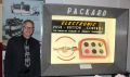
Here is a primer I wore on the Electrical Functions of the Torsion Level System, and how it is meant to work. This is not a how to diagnose chart per se, I will make one of those in the spring when I can resume work on my car, but tells you how the system is meant to work. Anyone with reasonable logic skills can read this and know where to trace power and continuity to make the system function.

Here is a little primer on the automatic leveling feature of the Torsion-Level suspension. There is a switch located on the lower lip of the instrument panel, to the left of the steering wheel. It powers the compensator timing box on the chassis. Left is off, right is on.
The compensator timing box located under the car has a rotating arm that has a center detent. It swings left or right as indicated by the blue arrows. This arm is linked to the driver's side full length front torsion bar , the rotation of that bar causes the switch to travel to either side of center. It is connected to a set of electrical contacts inside the Timing box marked "A" in this photo. When the car is level this contact is open. When a non-level state occurs the contact closes in the appropriate direction.
This sends +12 V power to the time delay switch marked "B" , to the coil for that direction. This coil acts as a heating element, as the power is applied the wire gets hotter, causing the long "U" shaped bimetal secondary contact to bend towards its contact. This heating/bending process takes 5-7 seconds to happen, this is the time delay feature to insure that the non-level state is constant, not a momentary event like a bump.
When one of those contacts closes it sends power to the corresponding relay, marked "C&D", closing that relay which sends a GROUND (not +12V) to the corresponding motor control solenoid, through the limit switch for that direction of travel. If the car is too far up or down, one the limit switches will open and prevent the system from operating, they are wired in series with the wire that sends GROUND to each solenoid.
The solenoids that power either side of the leveling motor receive +12V power for the pull-in coils internally and are seeking a ground to complete the circuit. The solenoid engages, the motor turns, cranking the intermediate bars to level the car. When they reach a level state switch "A" opens and the system is at rest until the next non-level state occurs. This is the 1956 system. 1955 is basically the same, except the world is out of 1955 boxes. This happened in 1956, so Packard made a retrofit wiring adapter to use the 1956 box on 1955 cars,


Click to see original Image in a new window


Click to see original Image in a new window

Posted on: 2/13 13:04
 Top 


Re: Mojave Tan - A 1956 400 Saga
#10
Forum Ambassador
Forum Ambassador

Mr.Pushbutton
Kevin-I'm late to the game with this post. I read through every response to this point. The Torsion Level limit switches suffer from age-related issues and become unreliable. I rewire these for clients, which is usually the problem. I have observed that car guys that are great mechanics are rarely good at soldering or frankly anything electrical. That's why most of the V8 Packards out there with their original wiring have just become Red/Blue/Yellow crimp splice hell. Here are some progressive photos of What I do with these switches. First thing is I test them with an Ohm Meter to see if they are still functional. Most are, just have deteriorated solder connections at the terminals and petrified insulation. A lot of these maladies are why people bypass the timing box on the chassis and wire in manual switches, and they always wire them in the dead-wrong way, bypassing the protection of the limit switches. That 69 year old wire doesn't owe you anything, it's time for all new wire for the entire T-L system, with properly made solder connections, not crimp splices. As my old boss used to say "Those crimp splices/terminals are for kids putting stereos in their jalopies."
Click to see original Image in a new window


Click to see original Image in a new window


Click to see original Image in a new window

Posted on: 2/13 12:58
 Top 


TopTop
(1) 2 3 4 ... 107 »


- Logged-in users will not see the following Adverts. Please Join (it's free) and Donate to help support the website -


- This above Google Ad-Sense Advert helps fund the cost of providing this free resource -
Search
Photo of the Day
Packard 1932 Twin Six 2d rdst…
Recent Photos
Recent Registry
Upcoming Events
AACA Fall Meet (Hershey)
10/06/2025 - 10/10/2025
South Pacific Packard Club 2026 Rally
03/22/2026 - 03/28/2026
Website Comments or Questions?? Click Here Copyright 2006-2025, PackardInfo.com All Rights Reserved