|
Fuel tank and outlet
|
||||
|---|---|---|---|---|
|
Home away from home
|
This is the sumped fuel tank sitting on a wooden trial-fit stand (for height and position). The view is from the rear of the frame. The outline and aluminum line (3/8IN) to the right go to a NAPA 3/8IN "Gold" fuel filter:
 This view towards the rear immediately to the P-side of the fuel tank. It is a Carter 15PSI electric rotory vane fuel pump. I used it because it had it. A 7PSI one would probably work as well. The line coming from the right is from the fuel filter. The line going to the left curves around inside the P-side frame rail. The mount is home made, but has rubber insulators to isolate the vibration.  The fuel feed line going forward is all one piece of aluminum 3/8IN tubing. This view shows it routed over the rear axle cross member and the "S-bend" over the rear T-L bars and load arm. This is the routing that Packard used on T-L cars, but my feed line goes on the P-side, not the D-side. The rubber hose around the feed line is not a connection, but is to prevent chaffing and wear on the aluminum tube.  The fuel feed is routed through an enlarged clearance hole with rubber fuel line insulation at the right rear outrigger (note the proximity to the T-L main bar through the frame. 
Posted on: 2015/5/7 17:08
|
|||
|
Nuke them from orbit, it's the only way to be sure! Ellen Ripley "Aliens"
Time flies like an arrow. Frui |
||||
|
||||
|
Fuel feed at the front
|
||||
|---|---|---|---|---|
|
Home away from home
|
Fuel feed line routing through the front outriggers is similar to shown in the previous post. The two tricky parts were the "S-bend at the front outrigger to clear the rear of the fenderwell and the routing under the upper control arm to keep the feed line away from the heat of the engine and headers.
 Despite the view, the fuel line is NOT being pinched by the upper control arm in the down (no load) position. The upper control arm rebound bumper is not yet installed and of course there is no weight on the frame because the body and fenders are not installed.  
Posted on: 2015/5/7 17:26
|
|||
|
Nuke them from orbit, it's the only way to be sure! Ellen Ripley "Aliens"
Time flies like an arrow. Frui |
||||
|
||||
|
Fuel Pressure Regulator, Mech pump & return
|
||||
|---|---|---|---|---|
|
Home away from home
|
Once the fuel feed line delivers fuel to the Holley fuel pressure regulator, it is at 15PSI (maybe a little less). The pressure needs to be reduced to 5PSI so as to not overwhelm the fuel pump and carb needle/seats. This is the arrangment and mounting I used. The U-loop rubber hose (FI grade fuel hose) is to allow motion of the engine under severe acceleration and deceleration.
 The mechanical fuel pump is a Carter M6905 for Ford FE 352-428 engines. It fits correctly on the Packard V-8 and has the right lever arm and eccentric stroke. It is not plumbed for the outlet to the carbs in the above picture. The regulator mounting bracket is custom. The regulator outlet is 1/2IN aluminum and follows the same routing to the rear in a mirror image of the feed line. 1/2IN tube was used to assure that the pressure could be reduced from 15PSI to 5PSI at the regulator.  This last picture is the return line connected into a "T-fitting" at the original fuel tank vent line to the fill tube.  Any questions or comments are welcome. Craig
Posted on: 2015/5/7 17:36
|
|||
|
Nuke them from orbit, it's the only way to be sure! Ellen Ripley "Aliens"
Time flies like an arrow. Frui |
||||
|
||||
|
Re: Craig's Panther Project -- Fuel system
|
||||
|---|---|---|---|---|
|
Home away from home
|
  
Posted on: 2015/5/16 12:54
|
|||
|
Riki
|
||||
|
||||
|
Craig's Panther Project -- Fuel Inlet System
|
||||
|---|---|---|---|---|
|
Home away from home
|
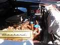
To complete the Panther fuel system, I have added a race car type fuel filler and inlet. One might ask "why?" as the stock inlet is quite functional. The main reason was to be able to seal off the filler door on the left rear fender to achieve a smooth fender line.
Here is a picture of the relocated inlet on the top of the left rear fender near the left trunk hinge. The part that shows is chrome and requires a special key to unscrew.  The next pictures show the plumbing. All hoses are special fuel resistant material and the 45-deg bends are mild steel mandrel bent exhaust tubing. Everything not black will be painted black and all connections will be secured by screw band clamp. Most connections will be welded where practical and duct tape removed as applicable.     Any questions or comments are welcome. Craig
Posted on: 2015/7/23 17:24
|
|||
|
Nuke them from orbit, it's the only way to be sure! Ellen Ripley "Aliens"
Time flies like an arrow. Frui |
||||
|
||||


