|
Re: Wes's Maroon 1947 Custom Super Clipper
|
||||
|---|---|---|---|---|
|
Forum Ambassador

|
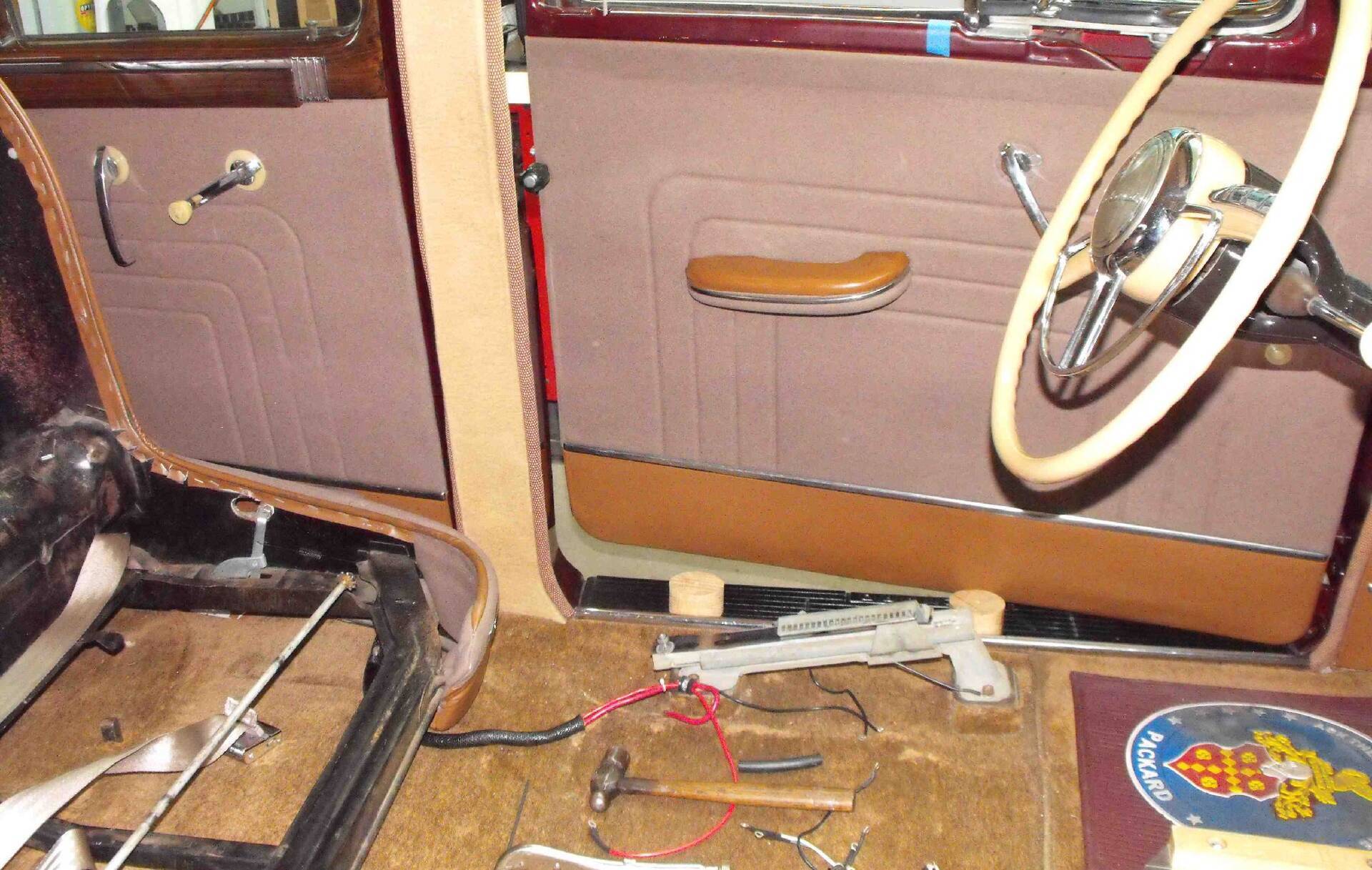
It is a bit easier to remove the frame from the tracks and move it toward the back seat although it is still heavy. If you just want space to work under the dash and nothing else in the interior is coming out or being worked on then maybe the best way. If your seat travel is rough or hard to slide I would suggest also taking the tracks out for a thorough clean and soak in solvent while the frame is off. Mine had layers of dried grease mixed with dirt and lint in the tracks to the point the seat barely moved.
Posted on: 2020/7/16 20:41
|
|||
|
Howard
|
||||
|
||||
|
Re: Wes's Maroon 1947 Custom Super Clipper
|
||||
|---|---|---|---|---|
|
Home away from home
|
Howard, that's how it normally goes. Goto work on one thing and then, well while I'm here it looks like I need to look into this or that. The fun never ends but once it's done that's it. I'll probaly look at the under seat heater also.
Wes
Posted on: 2020/7/16 20:59
|
|||
|
||||
|
Re: Wes's Maroon 1947 Custom Super Clipper
|
||||
|---|---|---|---|---|
|
Home away from home
|
Correct again Howard, by just moving the seat back gave me enough room to slide under the Steering Wheel. Now with both sides rewired and all the wires connected up correctly and loosing about five pounds of sweat. I found my Directional Switch only works for Right Hand turns. Well I was planing on taking out the Steering Column and cleaning it up along with realigning the Shift Linkage. So for now I'm leaving the wiring to the headlights as is and look into adding the power relays at a later time. The easiest way to check the Directional Signal Switch is to run a jumper from L on the back of the Flasher to one of the two junction blocks and that will simulate the switch being activated.
Wes
Posted on: 2020/7/18 20:32
|
|||
|
||||
|
Re: Wes's Maroon 1947 Custom Super Clipper
|
||||
|---|---|---|---|---|
|
Home away from home
|
Or you just always make right hand turns.... I'll have to see what your steering column looks like. My 1946 doesn't have turn signals.
John
Posted on: 2020/7/18 21:16
|
|||
|
||||
|
Re: Wes's Maroon 1947 Custom Super Clipper
|
||||
|---|---|---|---|---|
|
Forum Ambassador
|
Quote:
The easiest way to check the Directional Signal Switch is to run a jumper from L on the back of the Flasher to one of the two junction blocks and that will simulate the switch being activated. Agreed. Up thru the 22nd series the turn signals have a rather simple circuit. Here is an quick extraction showing just the basic connections of the turn signal wiring. The indicator lights actually both connect directly to the flasher P terminal unlike the single connection and splice that I show. I will fix the drawing one of these days -- probably when I manage to crawl under my dash and measure the value of the resistors on the indicator lights. Attach file:  (53.98 KB) (53.98 KB)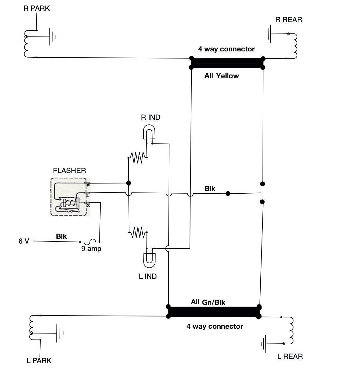
Posted on: 2020/7/18 21:39
|
|||
|
Howard
|
||||
|
||||
|
Re: Wes's Maroon 1947 Custom Super Clipper
|
||||
|---|---|---|---|---|
|
Home away from home
|
Howard, I like that you color coded your diagram but all of my wires are about the same color a Tan. The years have not been good to the wires. ;^)
ptv, I would like to see a photo of your column, because I have never seen one without the Directional Signal installed. Also checkout the following link:https://packardinfo.com/xoops/html/modules/newbb/viewtopic.php?topic_id=21586&forum=2&post_id=209908#forumpost209908 Wes
Posted on: 2020/7/19 8:59
|
|||
|
||||
|
Re: Wes's Maroon 1947 Custom Super Clipper
|
||||
|---|---|---|---|---|
|
Home away from home
|
Here you go Howard, will this work.
ptv, Here's a basic breakdown of the switch. Wes Attach file:  (54.01 KB) (54.01 KB)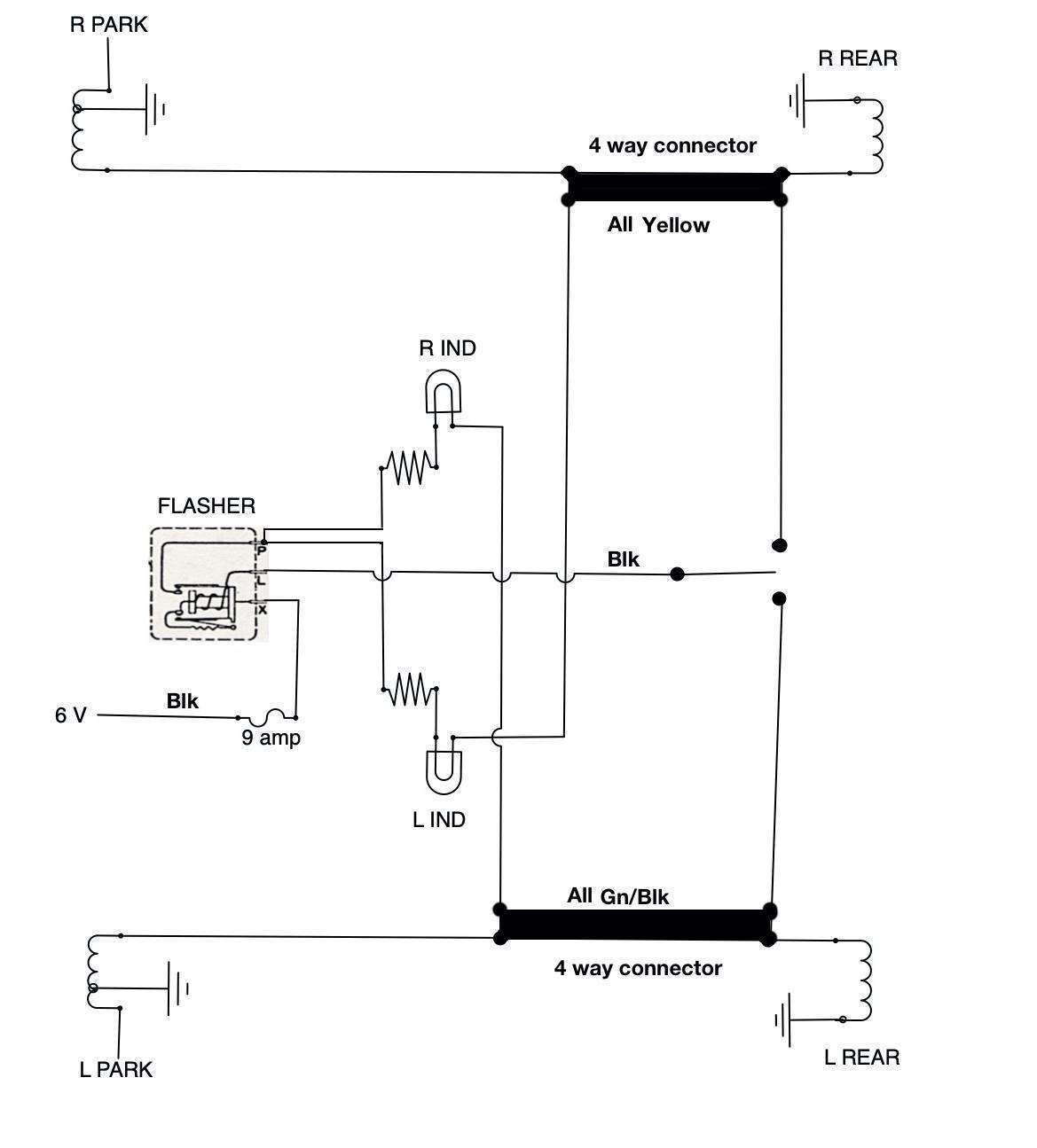 (136.73 KB) (136.73 KB)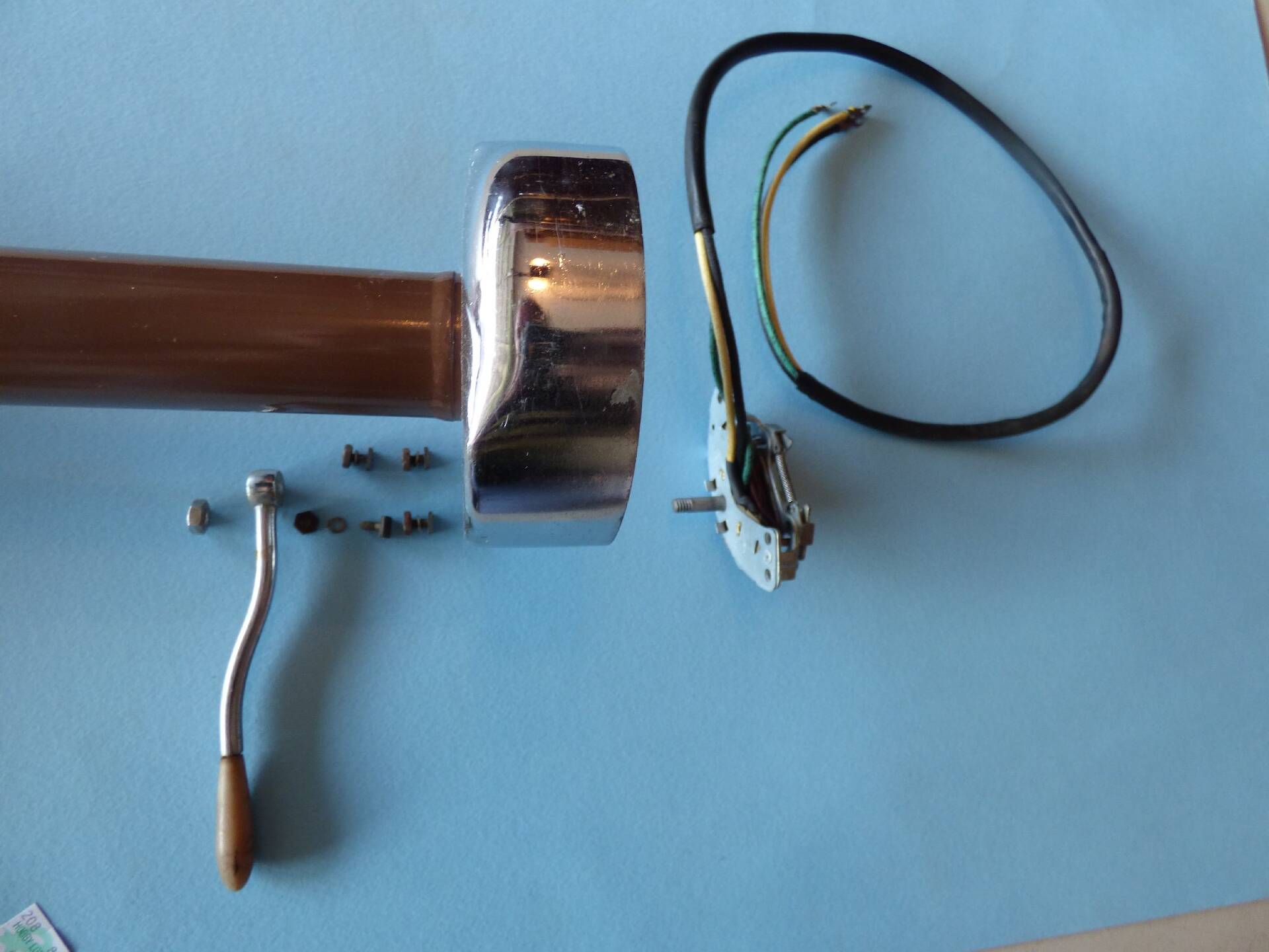
Posted on: 2020/7/19 13:38
|
|||
|
||||
|
Re: Wes's Maroon 1947 Custom Super Clipper
|
||||
|---|---|---|---|---|
|
Home away from home

|
It appears that the left indicator connects to the right lights and that the right indicator connects to the left. How does it work this way and what are the indicator resistors for?
Posted on: 2020/7/19 13:43
|
|||
|
||||
|
Re: Wes's Maroon 1947 Custom Super Clipper
|
||||
|---|---|---|---|---|
|
Forum Ambassador
|
The contacts in the flasher operate both the signal lights and indicator lights at the same time. The signal bulb total resistance needs to be a specific value to make the thermal type flashers work properly so that is probably the reason the indicator bulbs are on a separate output and not in parallel with the signal bulbs -- plus some cars only have one indicator light.
In this circuit, both indicator lamps are powered together from the P output but by having them connect to opposite sides, when one side is active the indicator light for that side can get its ground by going thru the filament(s) in the turn signal bulbs on the other side. If the indicator light was connected to the turn signal wires on the same side both wires to the indicator light would be at the same potential at the same time so the bulb would not light. In a single bulb indicator system the bulb would just have a regular ground. Not sure why the resistors are on the indicator bulbs but cutting the briteness or heat generated near the plastic lenses in the dash openings might be one reason.
Posted on: 2020/7/19 14:20
|
|||
|
Howard
|
||||
|
||||


.jpg")


