
|
Re: Solved: Vibration Damper Removal - 1928 5-26
|
||||
|---|---|---|---|---|
|
Quite a regular

|
28pack526
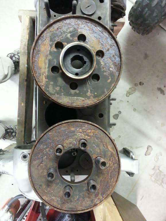
I have two engines for my 626 and have disassembled the damper. Yours seems very similar. The flywheel halves (part #147208) are a slip fit on a brass sleeve (part #158782)(upper picture of your flywheel halves) which is sandwiched between the hub (part #158729) and flywheel outer and inner bosses. The two halves of the flywheel are locked together by the springs (part #148434) and allows some movement in your case. My two halves actually have dowel pins and a friction ring (rubber composite) to further dampen this movement. As I see it the flywheel assembly is able to rotate on the keyed hub to find the best balancing point. To add a little friction to this operation sandwiched between the hub flange and one flywheel half and the pulley flange and the other flywheel half there is a phenolic friction disc (.125 thick)(part #146998 damper flywheel facing). In summary: The damper is separatable. Able to rotate as a unit on crank. Has minimal movement between two halves of the flywheel damper controlled by springs. Sandwhiched between keyed hub boss and fan pulley. Rotational movement controlled by friction disc. Will post some pics of the 626 damper soon. easyed ps side mounted water pump started after motor #238842 for the 626-633)
Posted on: 2014/3/28 16:50
|
|||
|
||||
|
Re: Solved: Vibration Damper Removal - 1928 5-26
|
||||
|---|---|---|---|---|
|
Just can't stay away
|
Hi easyed, My interpretation of this particular unit's functionality is that the rear flange, which is indeed keyed onto the hub, is locked in sync to the crank, but the outer flywheels are (or at least should be) free to move on the hub in response to engine pulses and are pressed against the drive pulley / rear flange by the 6 springs. A friction disk on the front between the damper and pulley would certainly make sense, but none was installed on mine when removed (just the two a fore mentioned steel shims).
Rather than lock it up as claimed in my last post, I think perhaps I'm going to CNC two 0.025" aluminum shim rings to place between the damper and pulley. That should impart some friction while still affording functionality. My caliper tells me that something with a 3-1/8" ID x 4-5/8" OD should work nicely...
Posted on: 2014/3/28 17:08
|
|||
|
||||
|
Re: Solved: Vibration Damper Removal - 1928 5-26
|
||||
|---|---|---|---|---|
|
Quite a regular
|
Hi 1928pack526
Your rear half of flywheel cannot be disingaged from hub? According to the parts book the 443/626-633/640-645 all have the same vibration damper hub sleeve (part #158782). Mine very definitely is free of the hub. (tight sliding fit to the hub and to the flywheel halves. (made of brass/bronze). The size of the facing ring is 3 1/8 ID 4 1/2 OD. Another reason I believe the rear half of your flywheel is detachable is that according to the parts book the 443/626-633/640-645 all have (2) identical vibration damper flywheel facing parts (part #146998) made from hard phenolic material. One for each side as mine does. easyed
Posted on: 2014/3/28 19:16
|
|||
|
||||
|
Re: Solved: Vibration Damper Removal - 1928 5-26
|
||||
|---|---|---|---|---|
|
Quite a regular
|
1928Pack526
Have you tryed pressing off the flywheel half from the keyed hub? I have a friend here that might have some parts as I already purchased from him a facing ring as one of mine was cracked. easyed
Posted on: 2014/3/28 19:29
|
|||
|
||||
|
Re: Solved: Vibration Damper Removal - 1928 5-26
|
||||
|---|---|---|---|---|
|
Quite a regular
|
hi 28Pack526
To further my point of complete disassemble all parts are listed and pictured separate. Is your brass/bronze sleeve sandwiched between the hub and flywheel? Will do some photography tomorrow and post them. easyed
Posted on: 2014/3/28 23:00
|
|||
|
||||
|
Re: Solved: Vibration Damper Removal - 1928 5-26
|
||||
|---|---|---|---|---|
|
Just can't stay away
|
Hi easyed, It sounds like our dampers are identical. In my previous post I said "rear flywheel" when I meant "rear flange", so I can understand the confusion. I've corrected that post for posterity.
The bronze sleeve on mine is pressed onto the inner hub. It's about 1/8" thick, and you can pretty clearly see it inside of the damper's top half in the picture I posted. Prior to disassembly, which took a considerable amount of force, the flywheels were completely fused together and to that sleeve by oxidation. As mentioned, my assembly had no friction disks, front or rear, just two steel shims clearly intended to bind the whole mechanism in place. If you have a line on two p/n #146998 disks, I'd be very interested. I assumed those would be unobtainable.
Posted on: 2014/3/29 8:29
|
|||
|
||||
|
Re: Solved: Vibration Damper Removal - 1928 5-26
|
||||
|---|---|---|---|---|
|
Home away from home
|
28pack526 guy; hi finley got the seal number for you, 471841-that is 2.5 o d which fits the cover when you knock out the felt seal holder. the bore size is 1.843 which the hub will need to be turned down to. hope the info helps u out. dell
Posted on: 2014/3/29 13:33
|
|||
|
35-1200 touring sedan 42-110 convertible coupe 48-2293 station sedan |
||||
|
||||
|
Re: Solved: Vibration Damper Removal - 1928 5-26
|
||||
|---|---|---|---|---|
|
Quite a regular
|
28Pack526
A couple of pictures of my later 626 vibration damper (part # 169559) You can clearly see the little metal lip that is the water thrower. The hub has a groove which I believe is for grease as has the brass sleeve. The picture is missing the springs, attachment bolts and inner pulley that works with the side mounted water pump. cheers easyed Attach file:  (65.76 KB) (65.76 KB)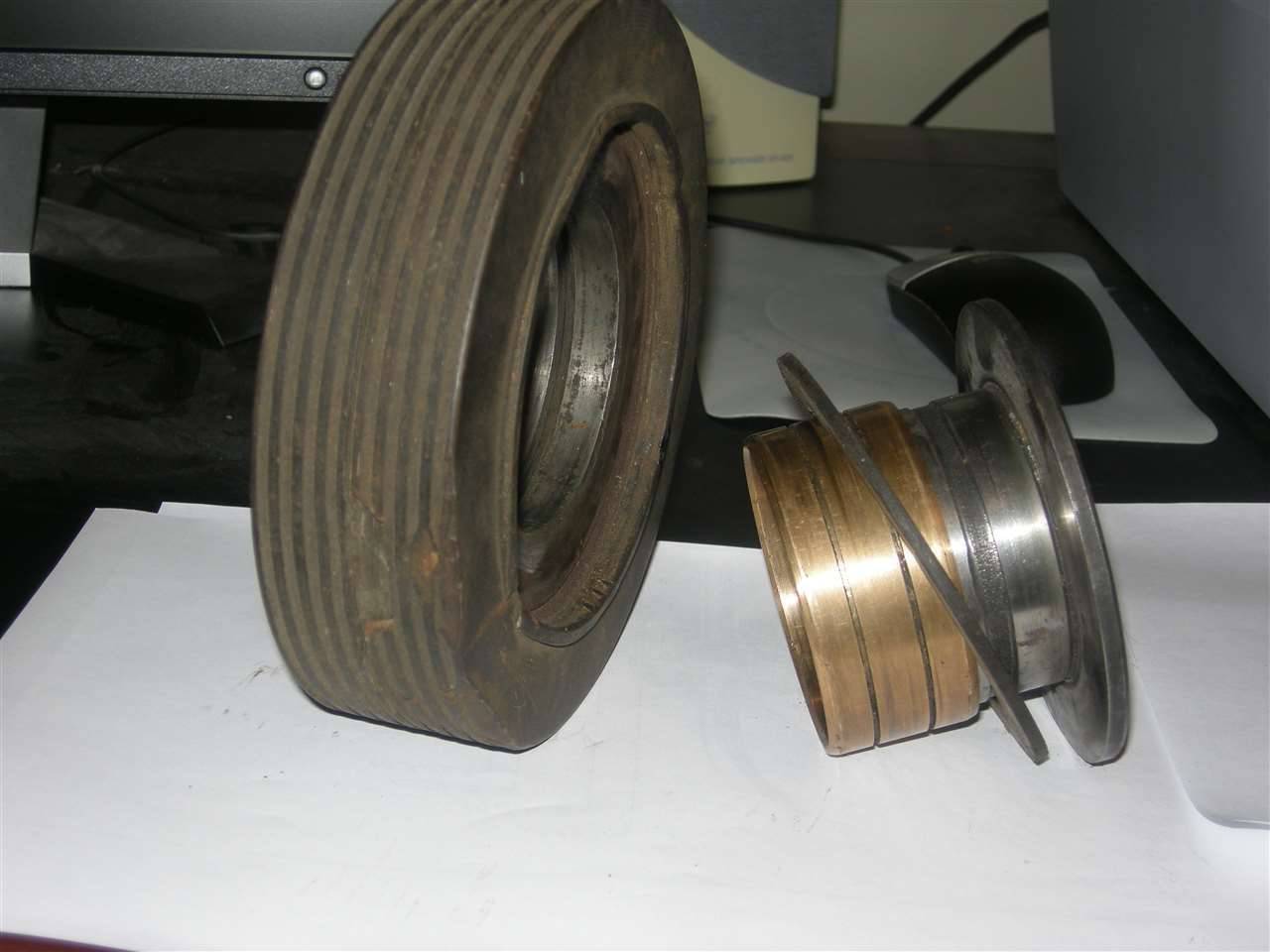
Posted on: 2014/3/29 23:41
|
|||
|
||||
|
Re: Solved: Vibration Damper Removal - 1928 5-26
|
||||
|---|---|---|---|---|
|
Just can't stay away
|
Thanks for the pics easyed. Here are some pics of my earlier design damper completely disassembled and prepped for paint, grease and reassembly.
The open circular piece surrounding the hub and springs is a ribbon of brass that slides into the flywheels' inside perimeter grooves. When assembled, it forms a complete circle, and is I suspect included to prevent water ingress. The only parts I didn't separate are the brass sleeve from the hub. It doesn't want to budge, and I see no reason to force the issue. Not pictured are the friction disks (p/n #146998) of course, because I don't have them. Attach file: (95.91 KB)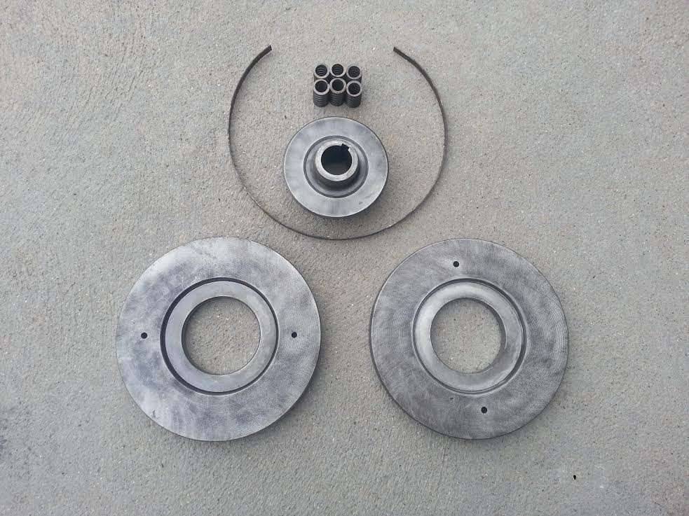 (78.74 KB) (78.74 KB)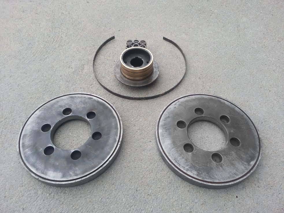 (57.98 KB) (57.98 KB)
Posted on: 2014/3/29 23:57
|
|||
|
||||


