
|
Re: Richter's '53 Caribbean
|
||||
|---|---|---|---|---|
|
Home away from home

|
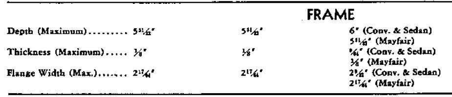
Looks like this says the Convertible and the Sedan share the same dimensions. The donor frame was from a sedan.
But even if it were the Mayfair, the biggest discrepancy is 1/32" of depth and 1/64" of width and thickness (if I'm reading it right). I'm pretty sure that's close enough to work just fine, but also close enough that I might have missed it with the micrometer. The Caribbean frame was rusted almost completely through in several places, and I wouldn't feel super comfortable driving a car with a welded frame, especially with a perfectly good frame right there. Even if it were different, it's not enough different to warrant spending $3000 on a donor car just to rip the frame out, so that it can be 1/32" taller. :) Good information to have though!
Posted on: 2015/3/30 9:25
|
|||
|
||||
|
Re: Richter's '53 Caribbean
|
||||
|---|---|---|---|---|
|
Home away from home

|
the frame on my 48 custom convertible has reinforcement on top and bottom of the X member. i sold my 53 convertible, therefore i can't check it out fore you. i would suggest you find a 53 or 54 convertible to look at, or get some pictures, you might be better off sand blasting your old frame and put fish plates over the bad areas.
Posted on: 2015/3/30 19:35
|
|||
|
35-1200 touring sedan 42-110 convertible coupe 48-2293 station sedan |
||||
|
||||
|
Re: Richter's '53 Caribbean
|
||||
|---|---|---|---|---|
|
Home away from home

|
that additional thickness in the frame was for structural soundness and integrity for the convertibles, the 51 through 56 Packard convertibles were very structurally sound cars due to this additional thickness. Remember that the 52/53 Monte Carlo show cars had cut roofs and greatly flexed (with doors coming open ) when going over railroad tracks due to the use of a non-convertible frame. The Packard engineers added beefed up the convertible frames for a reason
Posted on: 2015/3/30 23:44
|
|||
|
||||
|
Re: Richter's '53 Caribbean
|
||||
|---|---|---|---|---|
|
Home away from home
|
Quote:
i would suggest you find a 53 or 54 convertible to look at, or get some pictures, you might be better off sand blasting your old frame and put fish plates over the bad areas. Done this, since I had the original Caribbean frame to look at. I had the two frames side by side, measured outrigger distances and locations, and I've formed and welded the 1/8" flat strap steel plating over the top and bottom of the cross members, just as the factory had it, except the plating I used was a bit wider than factory. I'm pretty comfortable that the frame I have built up now is equivalent of, if not superior to (due to additional welding, and wider welding stock), the Caribbean frame that I had, even if the Caribbean frame I had were new and unrusted (although I wouldn't have gone to the trouble if the original frame could have been saved, because it's been a lot of extra work.)
Posted on: 2015/3/31 0:29
|
|||
|
||||
|
Re: Richter's '53 Caribbean
|
||||
|---|---|---|---|---|
|
Home away from home
|
Began radio rebuild today, since I finally managed to find a 6V power supply that will work.
For reference, it looks like it pulls at least 2 amps, so if you happen to find a wall plug that's 6VDC, make sure your amps is more than 2. Plugging the positive into the lead with the fuse on it, and negative to the chassis, I was able to get the bulb to light, but no noise from the speaker. Started taking apart the radio, not much on the outside was recognizable, so I was surprised to find a piece of paper nestled safely inside, in perfect condition after 60+ years, with the model number and tube layout for the radio. Remember when people used to be thoughtful like that? I don't. Two screws at the bottom to remove allows the back cover to come off which gives access to the tube compartment, which is where I found the diagram paper. I started by making a list of the tubes on a notepad, and looked them all up athttp://tdsl.duncanamps.com/tubesearch.php Without a tube tester, you can only do a basic test of the filament, so I was interested in finding out which pins were the heater/filament. In my particular set, 6v6GT (GT is Glass Tube, and functionally the same as 6v6, in case you need to replace). So in my set, 6v6GT x2, 6SK7 x2, and 6SA7, the heater/filament is from pin 2 to pin 7 (pin 1 is left of the notch, looking at the bottom, and goes clockwise, to 8 being right of the notch). the 2 6SQ7's are from pin 7 to pin 8. What this means is, like a light bulb, if you put an ohm-meter across the filament pins, you should get low, generally 4-6 ohms, but actual value doesn't really matter, as long as it's not open (tube burned out). 0Z4 or Oz4 I haven't found any info on. I lucked out and all of my tubes tested okay except for one of the 6SQ7s, which was in there so tight that my hand slipped and I threw it across the room. :P The filament actually still measured okay, but you could hear it rattle when you shook it. So add a step, gently shake the tube to make sure you don't hear anything loose. Not too hard though, a vacuum tube is essentially a light bulb. Looking through the back of the chassis, you should see the one wire that goes to the speaker, gently slide it out of the holder, remove the hex screws right around the front lip of the housing (about 10 of these), (and remove the nuts over the posts of the radio) and you should be free to remove the front cover (and the speaker with it). Looking in on this side, you can see the capacitors. They look like crayons that have been left under the car seat for a few years, and are about as useful. They'll all need to be replaced with newer orange drops of comparable value. Unfortunately, due to age and melty waxy goodness, good luck finding out what the values are without a schematic. I've ordered the schematic for this radio, and I'm going to go through my other radio kit to see if I just happen to have a 6SQ7 tube (probably not). Once I have the schematic, I can find the values of all the wax capacitors, and order the correct replacements. Replacement capacitors run between 5 cents and 50 cents a piece. Only the wax capacitors and electolytic capacitors need to be replaced unless there's an obvious issue. Mica caps and ceramics (and resistors) should be good for a lifetime. Generally, it'll cost you less than $10 in capacitors. Once you get them, just go one at a time, cut an old leg, solder a new leg, check and double check you're using the correct value until they're all done. Only electrolytic capacitors have polarity, the wax ones/orange drops you're replacing them with can go in either direction. Electrolytics you have to make sure the new cap goes in with negative on the same side as it comes out. For cosmetics and function: Everything chrome I hit with 000 steel wool and WD40, then buff with a soft cloth, and it made a huge difference. Not exactly show chrome, but much better than it started. Be very careful around the lens of the dial - it's plastic, so steel wool will scratch it by breathing on it. If it was glass it'd be safe. The buttons, they pull out to set the station, so to clean them, I steel wooled the whole assembly first, then pulled each out one at a time, and pushed the neighbor in so I could get the sides. While they're out, put a drop of 3 in 1 oil or other light oil on the arms where it slides out and in, work it back a few times. If it's hard to pull them out, then pull gently toward the volume knob side as you pull out. When working the oil in, I made a little oval, To the left and out, to the right and in, maybe a dozen times each to rub off the corrosion and rub in the oil. I added a drop of 3 in 1 oil to the tuning gear as well, and now everything moves smoothly. I'll update as I work more on this. My end goal is to add a phono input so that I can feed 40's, 50's, 60's songs from an mp3 player, but in such a way that it doesn't interfere with the regular operation of the radio. Guide to pictures: Radio 1 - starting point Radio 2 - Model and Tube Layout diagram from inside the radio Radio 3 - Before closeup of bezel Radio 4 - Before of Bezel Radio 5 - After cleaning Bezel Radio 6 - Before buttons Radio 7 - After buttons Radio 8 - chassis, front (speaker side, with caps) Radio 9 - chassis, front (another angle) Radio 10 - chassis, rear (tube side) Attach file:  (67.37 KB) (67.37 KB)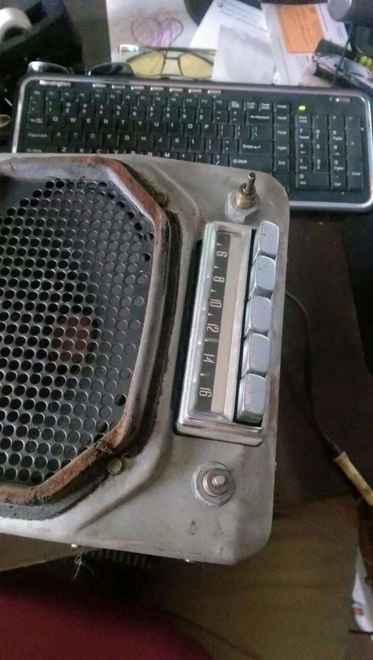 (55.99 KB) (55.99 KB)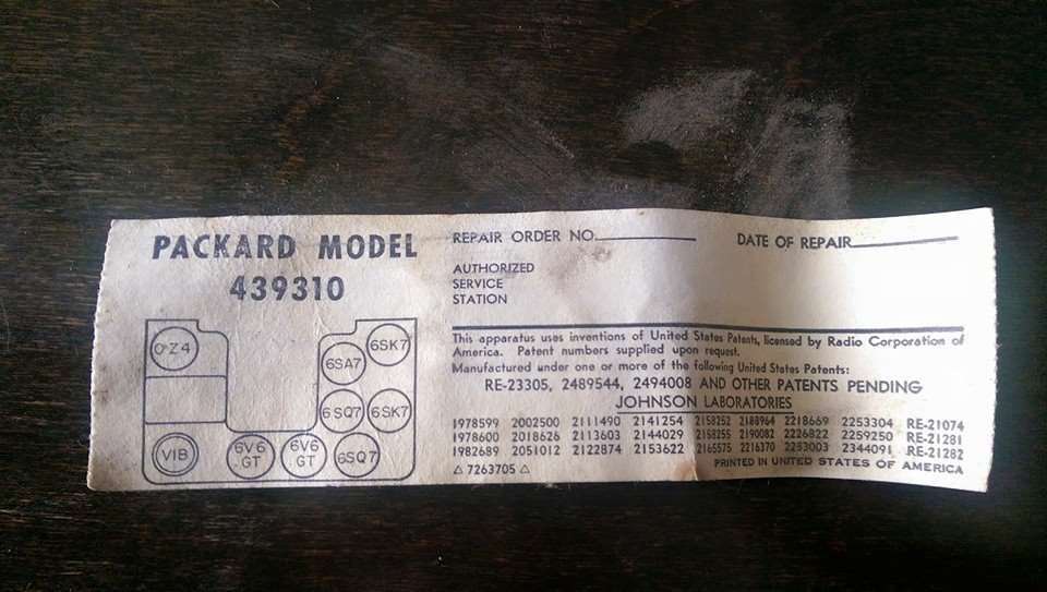 (81.39 KB) (81.39 KB)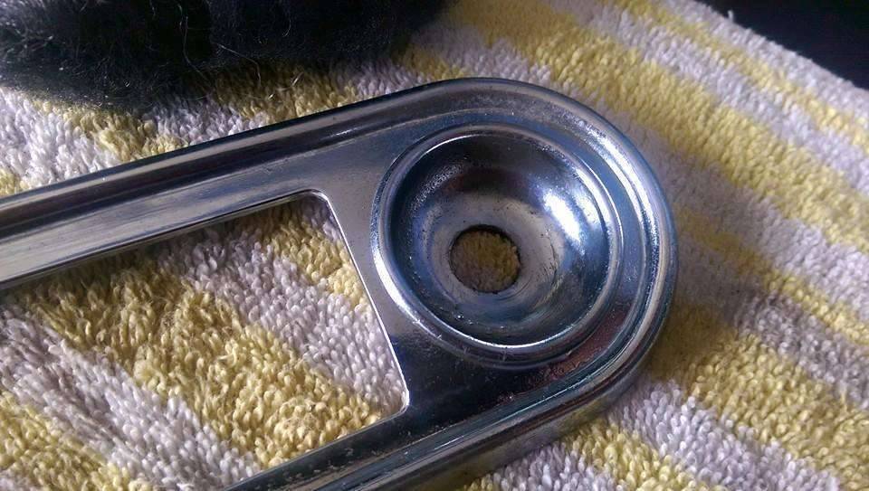 (80.63 KB) (80.63 KB)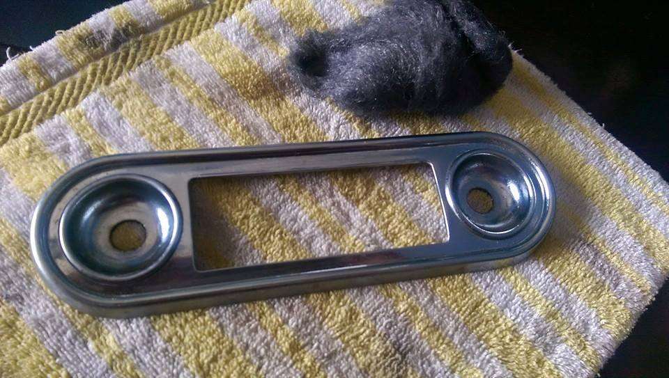 (48.14 KB) (48.14 KB)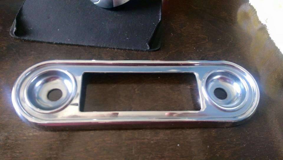 (58.11 KB) (58.11 KB)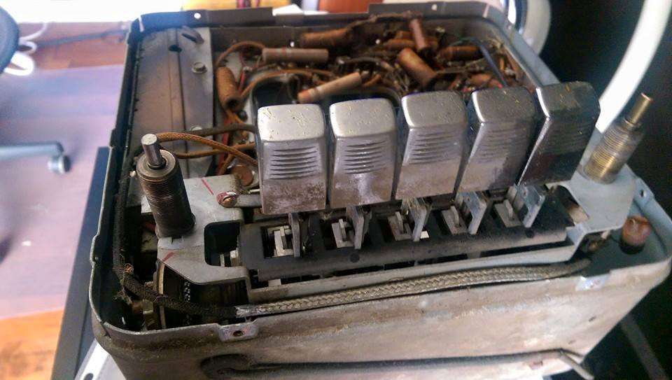 (57.36 KB) (57.36 KB)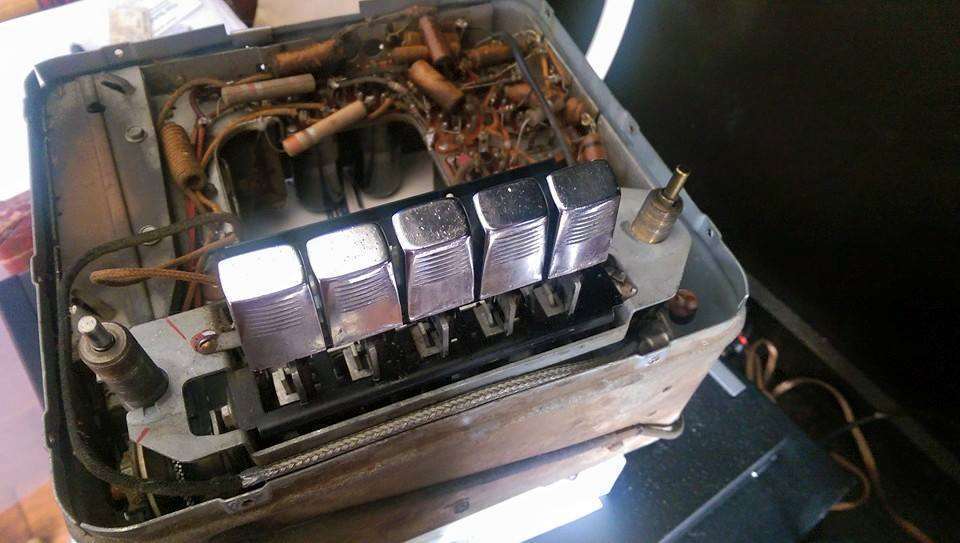 (58.40 KB) (58.40 KB)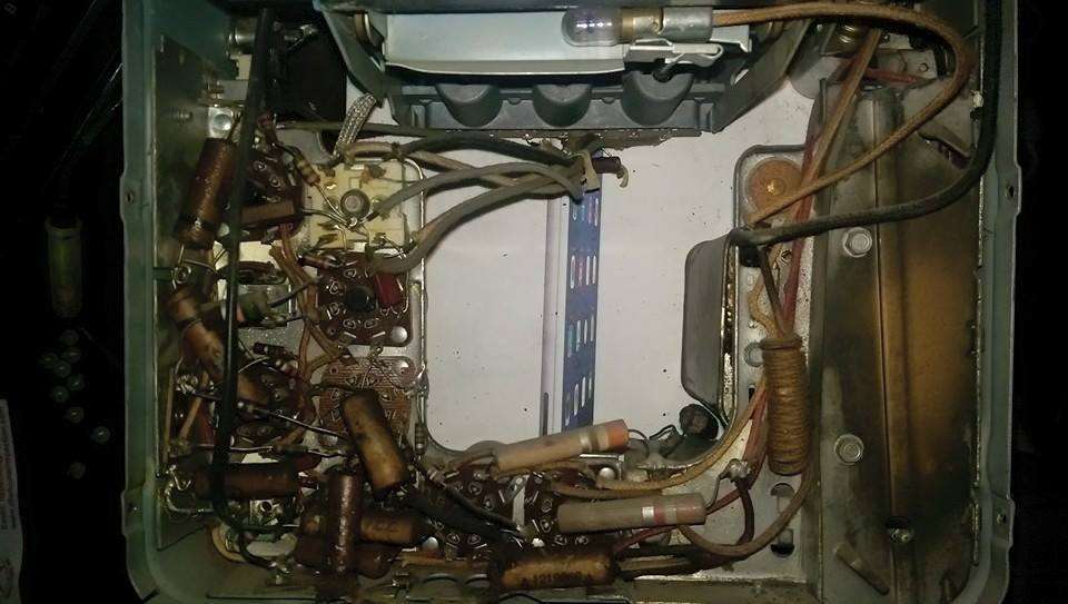 (69.50 KB) (69.50 KB)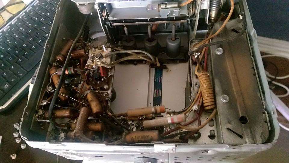 (57.91 KB) (57.91 KB)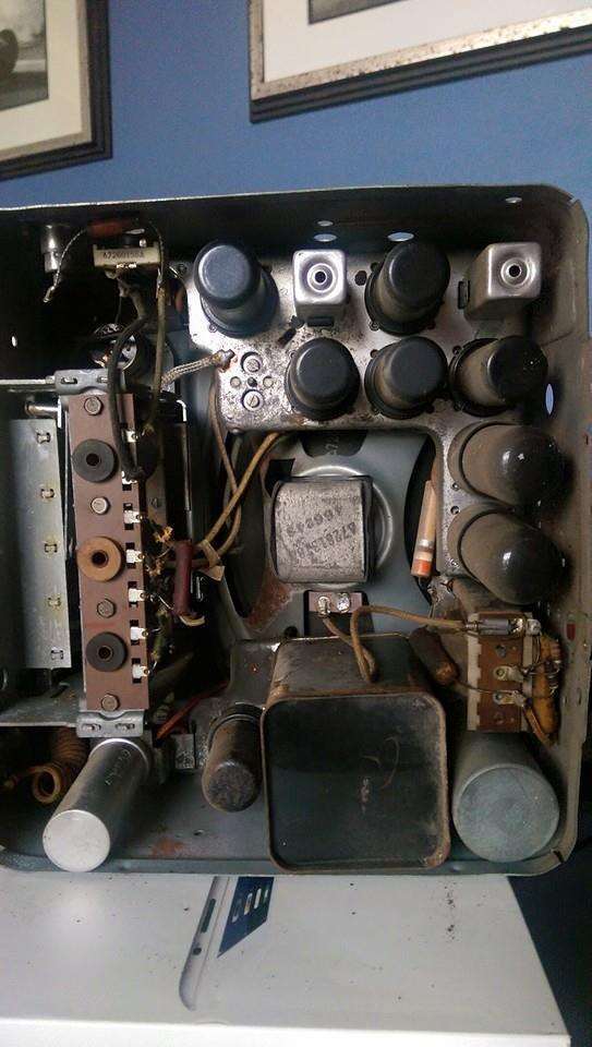
Posted on: 2015/4/1 13:26
|
|||
|
||||
|
Re: Richter's '53 Caribbean
|
||||
|---|---|---|---|---|
|
Home away from home
|
Looking good! You will find another capacitor under the metal panel on the right when you remove the two screws holding it down.
Although your station preset buttons are fancier than mine, I think internally we have the same radio. If so you can go to my project blog here and look under entry #135, below the third picture is a link to the schematic I used. You can also download a different version from this website. When you get to the part about adding the MP3 connection, please be as detailed as possible! I would love to know how it would work and I do not have much working knowledge with old radios. I have heard on other sites that there is a fear a power surge could go through the MP3 connection and ruin the MP3 player. Have you heard of this?
Posted on: 2015/4/1 14:46
|
|||
|
[url=h
|
||||
|
||||
|
Re: Richter's '53 Caribbean
|
||||
|---|---|---|---|---|
|
Home away from home
|
Quote:
When you get to the part about adding the MP3 connection, please be as detailed as possible! I would love to know how it would work and I do not have much working knowledge with old radios. Awesome! I'll take a look at that in a bit when I get a chance to fiddle again. The bit about power surge into the radio - technically it could probably happen because the chassis acts as the negative side, so if you were supply 10,000 volts to the chassis or something, that'd probably ruin your mp3 player. :) My MO is to use a cheap MP3 player, so that I can just leave it where it is - old iPods and offbrand mp3 players can be had for $20 with enough storage that you can listen all day and not hear the same song twice. Some of them even get FM. On the off chance something happened to it, it wouldn't hurt my feelings much. If it's a concern though, there's a project I was reading through where someone made essentially a short range AM transmitter, so it wouldn't even have to connect to the radio at all. That seems like a lot of work though. http://www.giangrandi.ch/electronics/am-mod/am-mod.shtml
Posted on: 2015/4/1 16:42
|
|||
|
||||
|
Re: Richter's '53 Caribbean
|
||||
|---|---|---|---|---|
|
Home away from home
|
I like thing original, I also work in electronics and am equipped to repair a car radio, soooooo . . . . .
When I restored the radio in my Cavalier I replaced the vibrator with a solid state version redially available from places like antique electronic supply in Tempe AZ. The next thing I replaced was the 0Z4 rectifier (a gas filled tube) which had DELCO printed on it and had probably been in there since 1954. This brought up the B+ voltage considerably and greatly improved the radio which was working. Be sure to match the vibrator to Neg or Pos ground. Most of the tubes were good when tested and no improvement when new ones were tried. When restoring antique radios or TV's of the late 40's through 50's we replace all of the paper capacitors. often the resistors have drifted off value so these should be checked. If you have the wonderBar tuning you will need to carefully clean the tuner section and inspect and possibly replace the rubber clutch's. Don't Lube with WD-40 ever. There are schematics posted on here for most of the radios which are so similar you probably won't need the exact model. The WonderBar Mech. is complicated and is not shown in the Sams literature and you will have to find a usable copy. I found the exact manual for mine on ebay for cheap. Jim
Posted on: 2015/4/2 12:39
|
|||
|
||||
|
Re: Richter's '53 Caribbean
|
||||
|---|---|---|---|---|
|
Home away from home
|
Easter weekend was a bit busy - but I managed to get the clamps for the leaf springs installed, and the sourced bushings worked perfectly. Cleaned up and repainted the shackles and the through-bolts for the front of the leaf spring, and got them both back on the frame.
Next step is to get the front suspension rebuilt (already have the rebuild kit waiting) and to go through and clean up the differential. It'll help a lot being able to just roll the thing in and out of the garage without having to balance it all on jacks. Heck, just getting one end or the other back on tires would help.
Posted on: 2015/4/6 10:28
|
|||
|
||||


.jpg")


