|
Re: Setting 3rd brush generator output
|
||||
|---|---|---|---|---|
|
Forum Ambassador

|
How does one know when he has the correct setting for the third brush?
A very easy question to answer but with a short answer that's not particularly helpful. The correct setting is the one that neither overcharges the battery (as indicated by frequent need to top up the water) nor undercharges it (as indicated by slow starting). Forget the voltmeter, it's got everything to do with amps. In a practical sense you want to have a charging rate just a few amps on the positive side for any particular load. And you may need several settings depending on driving situations. Here's how I've done my '34 for the past 50 years. Almost all of my driving is daytime driving, without any electric accessories, just running the ignition system, brake lights, etc. For this I set the 3rd brush to just compensate for the load, an ammeter reading of just positive by no more than 5 amps at average road speeds. Doing this, I rarely add water to the battery, and get about 7-8 years from a lead/acid battery. When the occasion occurs that I'll be driving at night, I'll adjust the 3rd brush so the ammeter is again just a few amps positive with all the lights on and whatever other electrical accessories you want want active. If your driving is almost exclusively very short trips with lots of restarts, you'll want a little higher rate. If it's long stretches of highway driving with few restarts, then a little lower. As you can see, the object is have a charging rate that compensates for whatever load you've imposed plus enough to replace what was used in starting, but by a small margin to prevent overcharging. In the day when folks found that whatever conditions they were in resulted in overcharging but they didn't want to change the 3rd brush, they simply drove with the headlights on to eat up the excess current - a pretty common practice in the days of 3rd brush generators. The cutout should open when the generator voltage is less than the battery voltage, visa versa for when it should open. Can't help with your other questions. Curious about the CD-840, my Owen-Dyneto listing doesn't show this unit ever used on a Packard. If you want to discuss getting a solid state generator control, I can't think of anyone better to speak with than Jason at AER. Attach file:  (84.28 KB) (84.28 KB)
Posted on: 2018/3/9 15:04
|
|||
|
||||
|
Re: Setting 3rd brush generator output
|
||||
|---|---|---|---|---|
|
Home away from home

|
Thanks O-D. Much appreciated. I don't suppose amperage decreases as the battery gets charged up (like in later cars) because there is no mechanism to control the amperage output.
The CD-840 is a curious story. The '24-'29 Eight Parts List shows it being used on all eights from first to sixth series. In fact, between p. 58 and 59 in that list there are several un-numbered pages with description of the CD-840, parts diagram, parts list and parts price list. Yet the Auto Electrician's Manual shows different numbers for the different series during this period. The only explanation I can come up with is 840 was a general designation for all 8 cylinder Packard generators made by Owen-Dyneto, and that the differing numbers shown in the Manual reflect the same basic Packard unit but with certain minor differences specific to certain year/series. Perhaps different charging specs: cut-in, max amps, etc. Mine, which is actually labeled CD-840, could have been a universal replacement ordered directly from Owen-Dyneto. Pure speculation of course. Attach file:  (111.19 KB) (111.19 KB)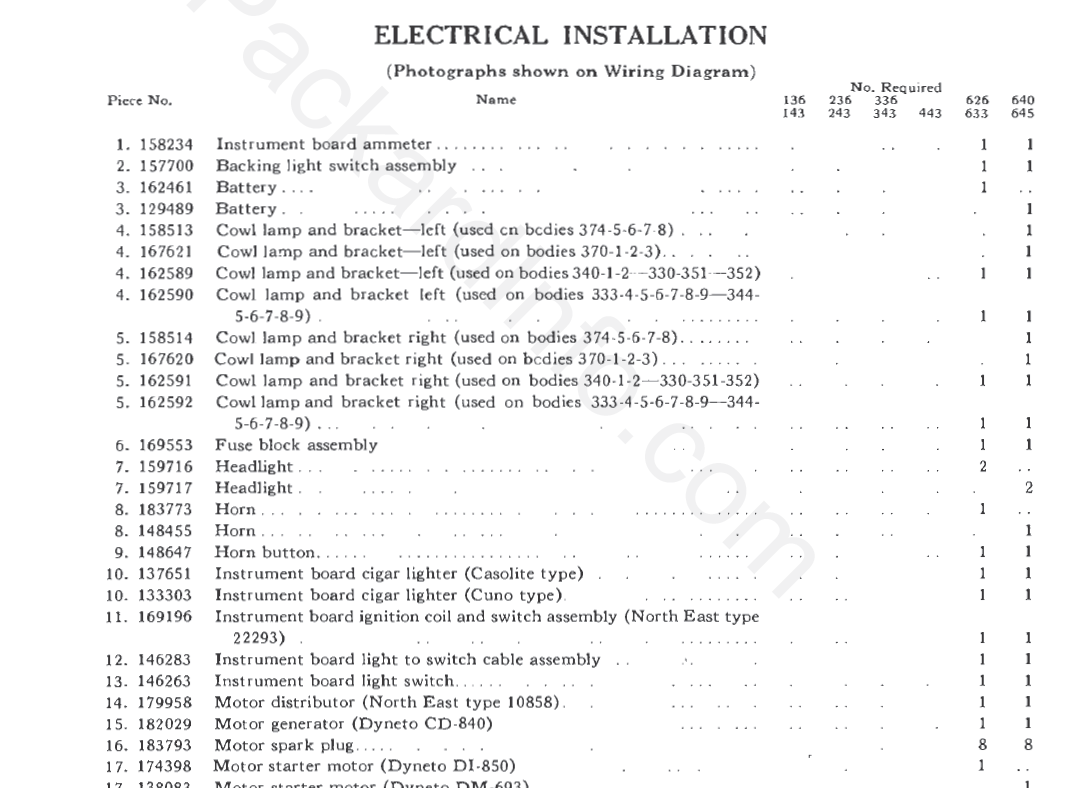 (27.35 KB) (27.35 KB)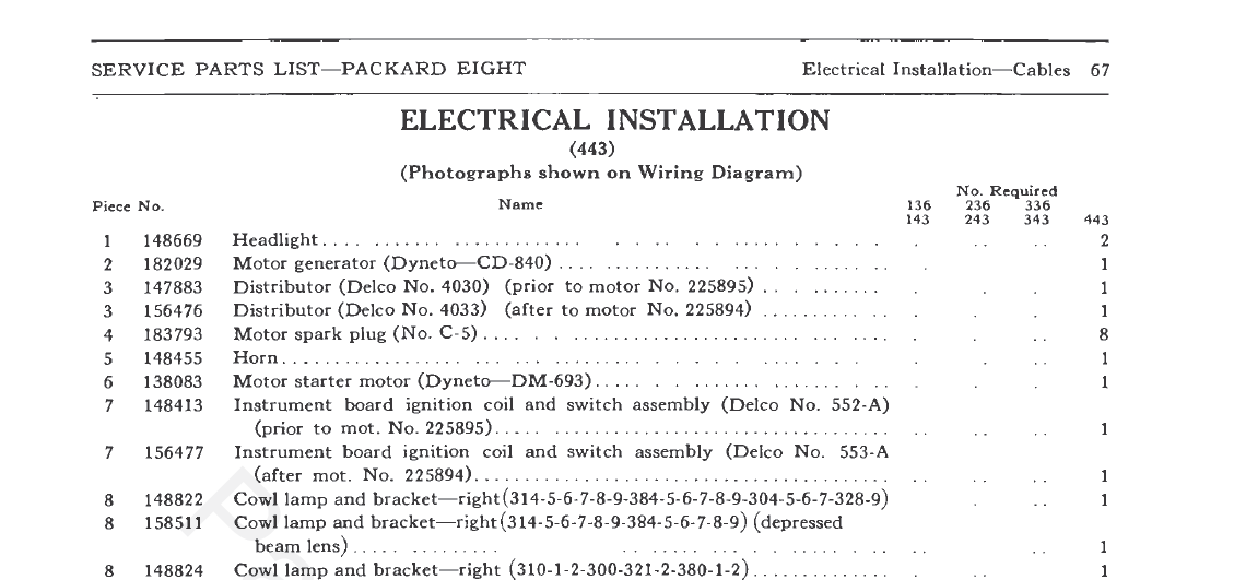 (47.83 KB) (47.83 KB)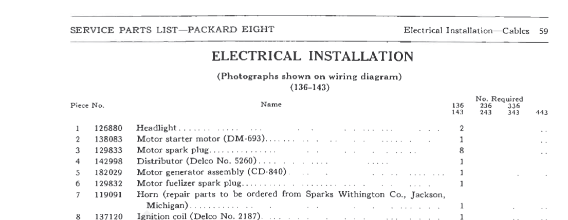 (43.32 KB) (43.32 KB)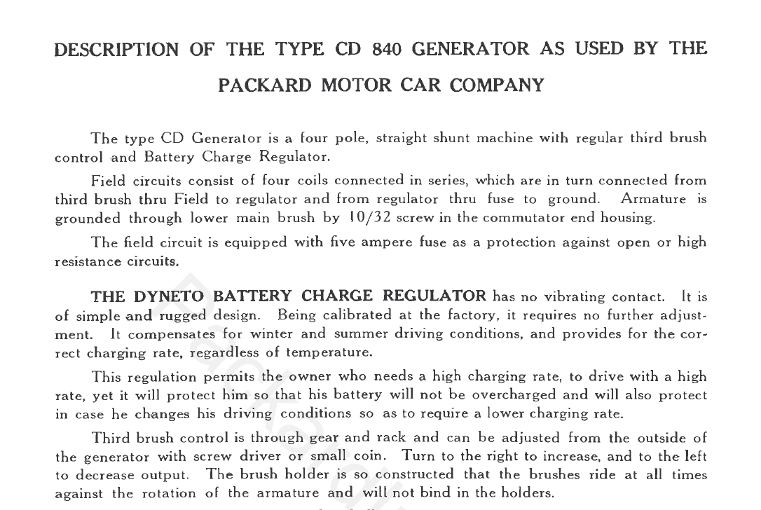
Posted on: 2018/3/9 20:24
|
|||
|
Rob
1930 Custom 8 Club Sedan |
||||
|
||||
|
Re: Setting 3rd brush generator output
|
||||
|---|---|---|---|---|
|
Home away from home
|
I may have the answer to the infamous CD-800, CD-840, CD-865 conundrum. On the 800 a simple cutout was used, so only the armature wire exited the generator case. The field wire was grounded through a fuse within the generator. On the 840, three wires exited the case as a regulator had been added to the 800 design. In addition to the armature wire, the field wire emerges and connects to the regulator terminal on the cutout/regulator. A third wire returns from the regulator to the fuse which is still located within the generator. In the 865, two wires exit the case, the armature wire and the field wire. The field wire connects to the regulator and thence goes to ground through a fuse within the regulator. There is no fuse in the case. Here are diagrams of the CD-840 and the CD-865.
Attach file: (66.77 KB) (355.72 KB) (355.72 KB)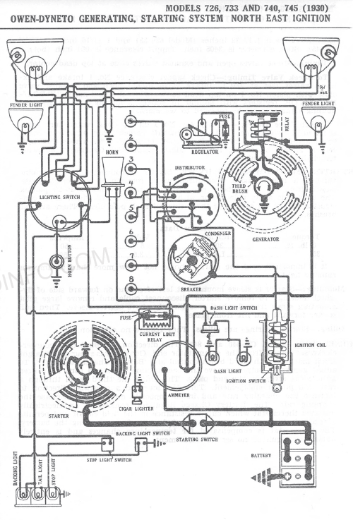
Posted on: 2018/3/19 22:19
|
|||
|
Rob
1930 Custom 8 Club Sedan |
||||
|
||||
|
Re: Setting 3rd brush generator output
|
||||
|---|---|---|---|---|
|
Forum Ambassador
|
Ah ha! Thanks for the info, that does clear up a lot of the confusion.
Posted on: 2018/3/20 6:35
|
|||
|
||||


.jpg")


