Re: 1941 1900 Packard heater
Posted by HH56 On 2015/7/13 11:51:28
There may be some simple sheets of operation material but as you have noted they are not that easily found. Wiring info was usually with install instructions or templates and in a few cases part of the service info but again not that often. There is a bit of accessory info showing a couple of heaters in the 41 fact book you can download here on site. Nothing shows the switches and other than a very generic illustration showing a basic heater circuit in one of the wiring diagrams, nothing specific for any particular heater.
I believe Packard had 3 or maybe 4 different heater/defroster combinations in 41 so info depends on which you have. AFAIK the accessories were all treated as standalone items and operating or wiring instructions would have been on the installation page that came with the accessory. For the most part the paper was thrown or filed away after the install was completed. In the case of operation, if it was new or different or complicated enough it might have had a small card or page to be placed in the glovebox but I believe anything needing that detail was more the exception.
The Dual Stream heater was under the seat and was just a fan controlled by a simple rotary 2 or 3 speed switch in a hang on bracket mounted under the dash edge. With the dual stream they typically installed a separate -- primarily defroster -- unit on the firewall which was capable of outputting a small amount of heat to the floor when defroster was on. That was also controlled by a simple (but separate) switch like the heater.
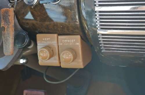
The Deluxe heater was a combination heater with a built in defroster section. It had a fairly elaborate 2 speed switch where center was off. Turning switch one direction caused the motor to rotate one direction and blow air out ducts to the windshield for defrost. Turning the switch the other direction caused the motor to rotate in the opposite direction and another fan blew air out the front of the heater box for the heater function. Because of the motor rotation and separate fan assys, both functions were not operational at the same time although there might have been a tiny bit of spillover air since both fans were rotating even if one was running backward.
There was a simpler and lower cost heater box available for under the dash on the firewall. It was mostly heater but I believe a separate blower assy controlled by a separate switch could be mounted on the top of the unit if the owner bought the defroster option for that heater. On that unit both functions could operate at the same time.
There is mention of a single motor combination heater and defroster with a 2 speed switch under the dash edge. While I have no specific info I believe that one had an option for some tubes or takeoffs that screwed on the back or side for the defroster hoses. Both functions could operate at once if doors were positioned nearly closed to force more air out the defrost ports or if more open, out the front for the heater.
There are some photos of the rotary switches being mounted in such a fashion the knobs were vertical on the bottom of dash edge. Some had a lever instead of a knob to provide a more toggle or slide like operation instead of pure rotary. On all heater versions, if installed in a Clipper the switches were different being push pull type with knobs styled to look like the other switches in the dash.
There was no temperature control as we know it today. A water shut off valve was on the head which you turned on in winter or when it got cold and off in summer. That allowed hot water to circulate thru the heater/defroster cores which were all plumbed in series so all were supplied with heated water all the time. Actual heat output was controlled by turning on a particular units fan and regulating fan speed. Once the fan was on opening or closing the heater doors would direct or partially block the airflow.
Some heaters and models had a fresh air option where a long metal tube or duct ran parallel to the engine up to the grill area. There was an opening cut in the firewall and outside air was introduced into the back of the heater assy. The air flow was controlled by a pull out knob which worked a small flapper door in the duct. On that type you could open the duct flapper door and not have to turn on the fan.
Don't remember where this photo came from but the car might belong to someone on the forum. It shows a typical install of 41 switches.
Attach file:
 (59.82 KB)
I believe Packard had 3 or maybe 4 different heater/defroster combinations in 41 so info depends on which you have. AFAIK the accessories were all treated as standalone items and operating or wiring instructions would have been on the installation page that came with the accessory. For the most part the paper was thrown or filed away after the install was completed. In the case of operation, if it was new or different or complicated enough it might have had a small card or page to be placed in the glovebox but I believe anything needing that detail was more the exception.
The Dual Stream heater was under the seat and was just a fan controlled by a simple rotary 2 or 3 speed switch in a hang on bracket mounted under the dash edge. With the dual stream they typically installed a separate -- primarily defroster -- unit on the firewall which was capable of outputting a small amount of heat to the floor when defroster was on. That was also controlled by a simple (but separate) switch like the heater.
The Deluxe heater was a combination heater with a built in defroster section. It had a fairly elaborate 2 speed switch where center was off. Turning switch one direction caused the motor to rotate one direction and blow air out ducts to the windshield for defrost. Turning the switch the other direction caused the motor to rotate in the opposite direction and another fan blew air out the front of the heater box for the heater function. Because of the motor rotation and separate fan assys, both functions were not operational at the same time although there might have been a tiny bit of spillover air since both fans were rotating even if one was running backward.
There was a simpler and lower cost heater box available for under the dash on the firewall. It was mostly heater but I believe a separate blower assy controlled by a separate switch could be mounted on the top of the unit if the owner bought the defroster option for that heater. On that unit both functions could operate at the same time.
There is mention of a single motor combination heater and defroster with a 2 speed switch under the dash edge. While I have no specific info I believe that one had an option for some tubes or takeoffs that screwed on the back or side for the defroster hoses. Both functions could operate at once if doors were positioned nearly closed to force more air out the defrost ports or if more open, out the front for the heater.
There are some photos of the rotary switches being mounted in such a fashion the knobs were vertical on the bottom of dash edge. Some had a lever instead of a knob to provide a more toggle or slide like operation instead of pure rotary. On all heater versions, if installed in a Clipper the switches were different being push pull type with knobs styled to look like the other switches in the dash.
There was no temperature control as we know it today. A water shut off valve was on the head which you turned on in winter or when it got cold and off in summer. That allowed hot water to circulate thru the heater/defroster cores which were all plumbed in series so all were supplied with heated water all the time. Actual heat output was controlled by turning on a particular units fan and regulating fan speed. Once the fan was on opening or closing the heater doors would direct or partially block the airflow.
Some heaters and models had a fresh air option where a long metal tube or duct ran parallel to the engine up to the grill area. There was an opening cut in the firewall and outside air was introduced into the back of the heater assy. The air flow was controlled by a pull out knob which worked a small flapper door in the duct. On that type you could open the duct flapper door and not have to turn on the fan.
Don't remember where this photo came from but the car might belong to someone on the forum. It shows a typical install of 41 switches.
Attach file:
(59.82 KB)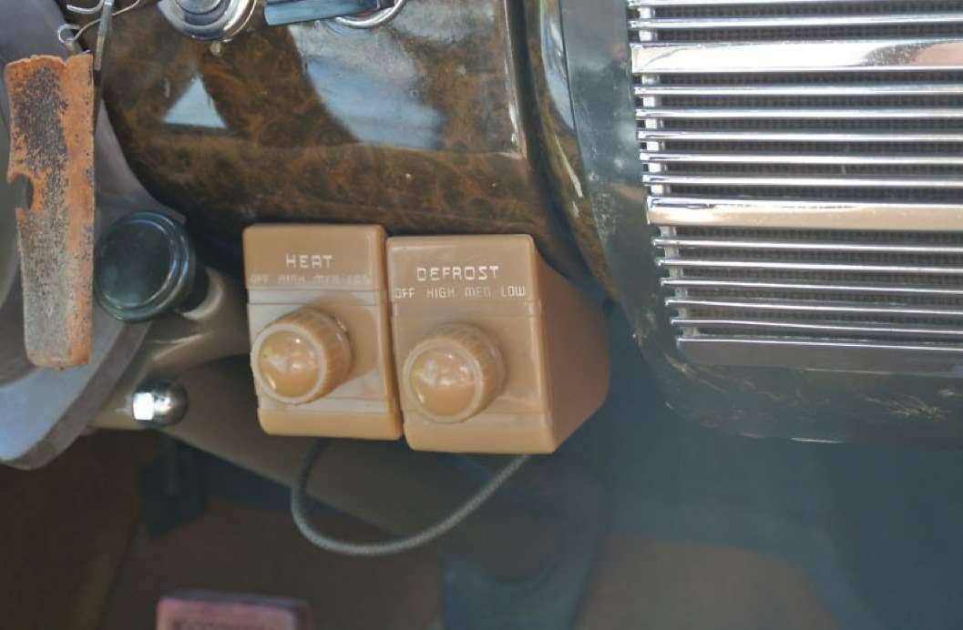
This Post was from: https://packardinfo.com/xoops/html/modules/newbb/viewtopic.php?post_id=164177