Re: Packard Heaters
Posted by HH56 On 2017/4/24 9:48:41
Your heater appears to be a 41 and later deluxe unit and the switch is an indash that was used on Clippers with a convenient knob attached. Not too familiar with 39s but believe the wiper knob is on top of the dash. Typically conventional bodies would have had their heater or other accessory switches in a plastic housing with the name and function etched into the face and mounted under the dash edge or as the 37 illustration showed, vertically in the dash edge.
It is interesting they chose to mount the heater the way they did. Maybe it was necessary on the earlier body but normally the small flat door is at the bottom so you can open it and have air directed to the feet and floor rather than going up under the dash. The vertical side doors open to direct and circulate air thru the car.
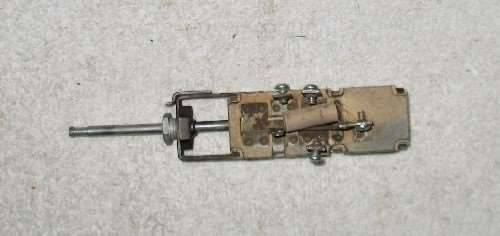
Your switch should have 4 positions. Off and then 3 for motor direction and speed. Someone else will have to verify the arrangement since I don't have that particular unit to play with but I believe the defroster is one speed and the heater portion has two. I don't know if the defroster or the heater comes on first but at some point the motor will be reversed to fulfill both functions. Once you get yours going I would be interested to know which position does what.
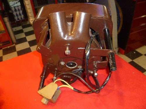
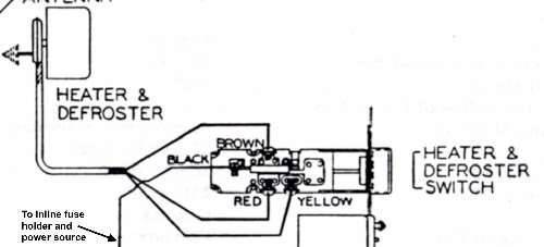
The power should come from the ignition switch thru an inline fuse holder. I can't see the bottom of your switch very well to see if a wire is present but power should be coming into the end terminal on the switch. There are 4 wires from the motor. Ground can be handled in any number of ways. On some it may be a separate wire fastened directly to the body somewhere close to the heater. On other heaters it is part of the loom and comes up to be attached to ground near the switch.
Here is a photo of the rear of the heater I borrowed from a current ebay listing. Note the typical rotary switch and plastic housing that would be used on your type body. Ground wire looks separate but can't tell if the ground is fastened with a sheetmetal screw to the back or continues on as part of a longer wire to attach somewhere else.
Also including a schematic of the hookup and a photo of a Clipper switch. I believe I can see red and yellow designating the wire colors stamped in the metal case on your switch just above the ceramic and terminals. If I am seeing things then the colors are on the schematic.
Attach file:
 (134.79 KB)
(51.70 KB)
(54.11 KB)
It is interesting they chose to mount the heater the way they did. Maybe it was necessary on the earlier body but normally the small flat door is at the bottom so you can open it and have air directed to the feet and floor rather than going up under the dash. The vertical side doors open to direct and circulate air thru the car.
Your switch should have 4 positions. Off and then 3 for motor direction and speed. Someone else will have to verify the arrangement since I don't have that particular unit to play with but I believe the defroster is one speed and the heater portion has two. I don't know if the defroster or the heater comes on first but at some point the motor will be reversed to fulfill both functions. Once you get yours going I would be interested to know which position does what.
The power should come from the ignition switch thru an inline fuse holder. I can't see the bottom of your switch very well to see if a wire is present but power should be coming into the end terminal on the switch. There are 4 wires from the motor. Ground can be handled in any number of ways. On some it may be a separate wire fastened directly to the body somewhere close to the heater. On other heaters it is part of the loom and comes up to be attached to ground near the switch.
Here is a photo of the rear of the heater I borrowed from a current ebay listing. Note the typical rotary switch and plastic housing that would be used on your type body. Ground wire looks separate but can't tell if the ground is fastened with a sheetmetal screw to the back or continues on as part of a longer wire to attach somewhere else.
Also including a schematic of the hookup and a photo of a Clipper switch. I believe I can see red and yellow designating the wire colors stamped in the metal case on your switch just above the ceramic and terminals. If I am seeing things then the colors are on the schematic.
Attach file:
(134.79 KB)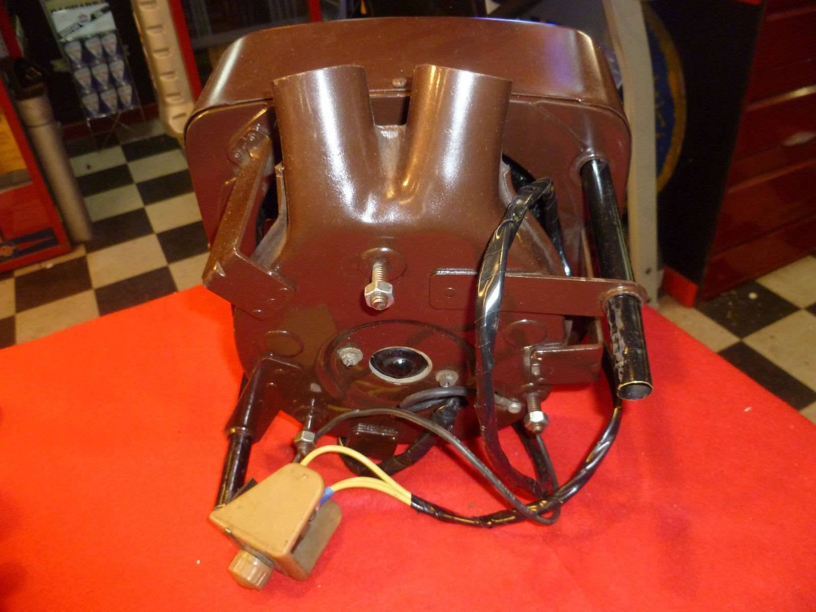 (51.70 KB)
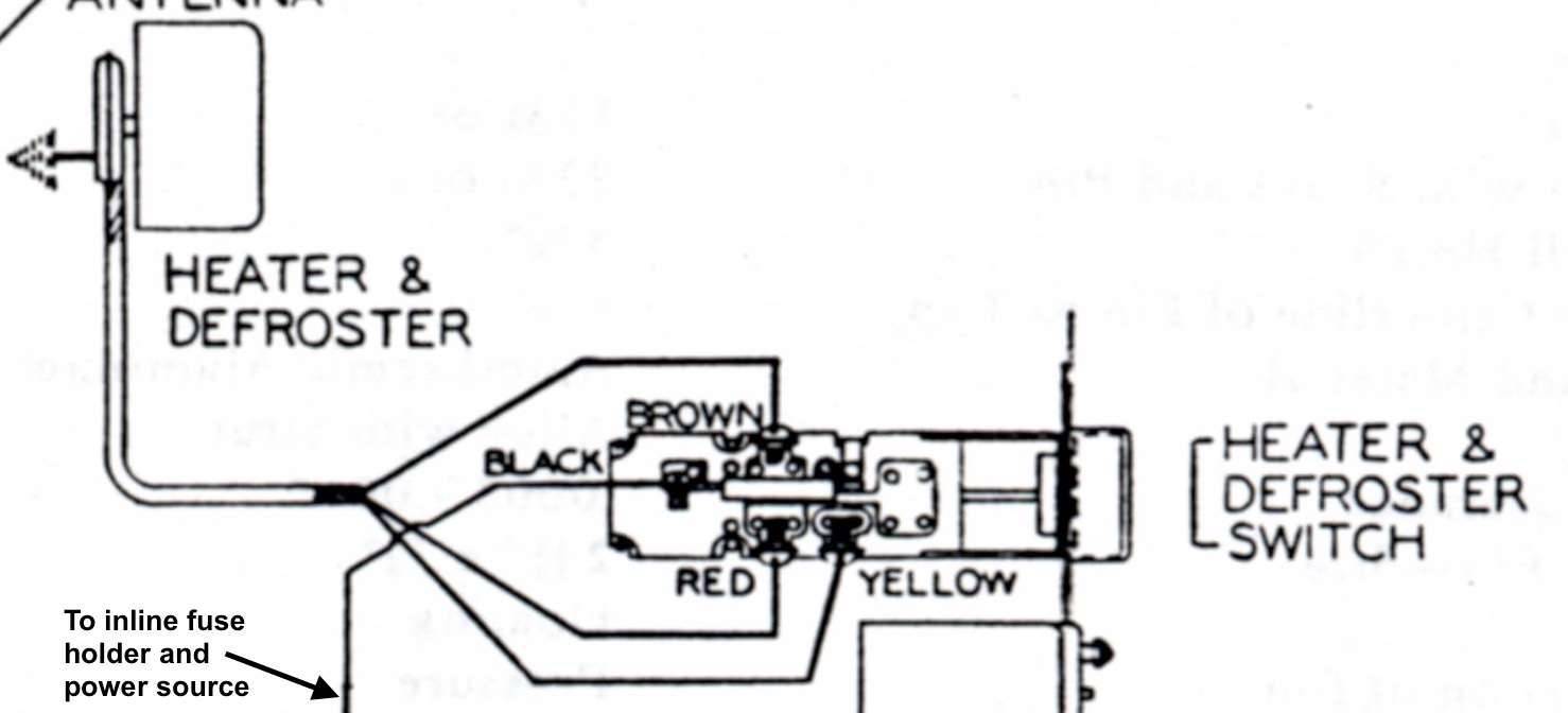 (54.11 KB)
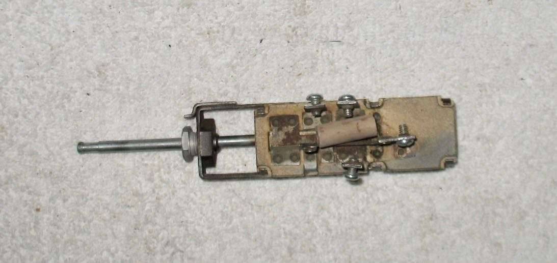
This Post was from: https://packardinfo.com/xoops/html/modules/newbb/viewtopic.php?post_id=190648