Re: Overdrive wiring issue
Posted by HH56 On 2019/4/2 10:12:14
Quote:
I think Ross has the right assumption that the screw you were working with has messed up the calibration of the governor. Providing there has been no damage you might be able to get it back in a workable condition but the contact action is delicate and could have been bent. There was a caution issued by the factory that the field should not mess with calibration as it took special equipment to calibrate them so getting yours back may take some time as you will need to drive, adjust and drive again until it is in a good range. In 40 they issued 3 governor backs calibrated at different speeds to accommodate different models and user preferences. In 41 they settled on one range but also advised the field that the earlier backs were compatible and if they had a customer that insisted on a different range they could use one of the differently calibrated items.
As to the question on reversed wiring it is possible that could be the cause of no solenoid but I would concentrate on the governor first.
OD Relay contact functions:
1 Power in
2. Ign cut out to coil
3. Power out to solenoid HOLD coil
4. Power out to solenoid PULL IN coil
5. Ground in from governor in series with other switches to pull in relays
6. Ign cut out from solenoid contacts.
If OD relay terminals 4 and 6 are reversed there would be power fed to a set of contacts used in the ign cutout circuit in the solenoid if the relay was energized. With no power going to solenoid terminal 4 the solenoid would not be able to pull in so the cutout contacts should be open and there would be no damage unless for some reason the cutout contacts were misadjusted or damaged in some other way. If that were the case there would be a direct short when the relay energized. You didn't say if you used a meter or a visual check to see if the wires were reversed. Visually the colors may have faded but the wire on relay 4 going to solenoid 4 should be larger than the wire on 6. Electrically with the meter, unless they were disconnected when testing there could be some feedback thru other components which might be clouding the issue.
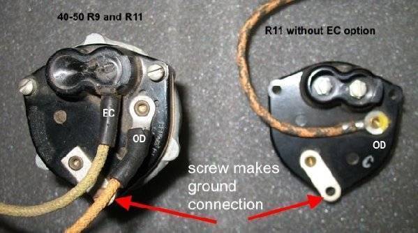
OD and EC circuits both rely on the governor grounding the wire but operate at different times. When the car is stationary the wire on the governor labeled EC in the photo is grounded and the wire labeled OD is just sitting open. That allows the clutch electrics to be active and provide vacuum to operate the mechanism so the clutch can do its thing. The OD is inactive because its relays are not pulled in. When the car reaches the set speed the contacts in the governor switch state so EC is now sitting open while OD is grounded. That action disables the EC and provides a signal thru other switches to terminal 5 of the OD relay. Relay energizes and provides power out to terminal 4 and thru the other relay coil in the box out to terminal 3 to bring in the solenoid. Both terminals need power out to the solenoid in order for the solenoid to engage. No power to 4 and there is no pull in coil so the solenoid cannot engage. No power to 3 and the pull in coil will bring the solenoid in until the motion makes the pull in contacts in the solenoid open and the coil drops out. Without the hold coil energized by 3 to keep the plunger out the cycle will repeat and the solenoid will "machine gun". The power out at relay 4 also provides power to the indicator light that the car is at speed. Does the light come on? Assuming the bulb and other wiring is good, if it does not then the governor ground signal is not reaching the relay and you can suspect calibration. If it does light then look to miswiring or another problem.
Prewar EC electrics are somewhat complex compared to the postwar EC and adds an additional wrinkle to the governor wiring because the EC also uses the OD wire signal to indicate when the car has reached cruising speed. That action energizes a relay in the EC box and brings other parts of the EC into play so the clutch can be made active at a specific time when cruising and you want to downshift. Not sure where the wiring is joined so both EC and OD can take advantage of the OD governor signal.
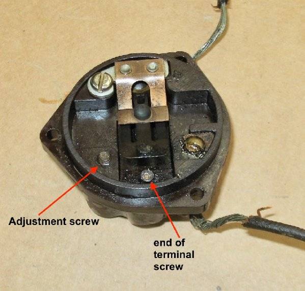
In the photos below, the proper adjustment screw is on the left (covered by tar in the R9 photo) and the contact terminal is on the right. There is a caveat in that the screw the wire attaches to threads into the base and normally is not touched. These governors have a locking nut on the terminal screw so the screw isn't threaded in too far. If that was the screw moved then on the bottom photo of the broken governor you can see that the extra length inside the governor can affect the adjustment and also move the fixed contact inward so as to prevent the switch moving contacts from making the proper action. That could provide a permanent connection to ground for EC and really change the point OD connects.
Attach file:
 (43.56 KB)
(33.02 KB)

(79.00 KB)
I tested the continuity of the wiring between the OD relay and the solenoid. Contacts 2 and 3 seem to be wired as shown in the OD training manual, however, the 4 and 6 terminals may be reversed. I know the wiring is correct at the relay, and believe it is correct at the solenoid, that is it is as it has always been, but again, I could be wrong.
What would be the effect if these two wires are switched? Can I reverse these without risking damage to the unit?
Just because grounding the governor earlier and having that grounding result in the solenoid pull-in and hold-in circuits working, it makes me think that the issue of not now engaging at speed is related to the governor. But I am not sure if that logic holds up.
I think Ross has the right assumption that the screw you were working with has messed up the calibration of the governor. Providing there has been no damage you might be able to get it back in a workable condition but the contact action is delicate and could have been bent. There was a caution issued by the factory that the field should not mess with calibration as it took special equipment to calibrate them so getting yours back may take some time as you will need to drive, adjust and drive again until it is in a good range. In 40 they issued 3 governor backs calibrated at different speeds to accommodate different models and user preferences. In 41 they settled on one range but also advised the field that the earlier backs were compatible and if they had a customer that insisted on a different range they could use one of the differently calibrated items.
As to the question on reversed wiring it is possible that could be the cause of no solenoid but I would concentrate on the governor first.
OD Relay contact functions:
1 Power in
2. Ign cut out to coil
3. Power out to solenoid HOLD coil
4. Power out to solenoid PULL IN coil
5. Ground in from governor in series with other switches to pull in relays
6. Ign cut out from solenoid contacts.
If OD relay terminals 4 and 6 are reversed there would be power fed to a set of contacts used in the ign cutout circuit in the solenoid if the relay was energized. With no power going to solenoid terminal 4 the solenoid would not be able to pull in so the cutout contacts should be open and there would be no damage unless for some reason the cutout contacts were misadjusted or damaged in some other way. If that were the case there would be a direct short when the relay energized. You didn't say if you used a meter or a visual check to see if the wires were reversed. Visually the colors may have faded but the wire on relay 4 going to solenoid 4 should be larger than the wire on 6. Electrically with the meter, unless they were disconnected when testing there could be some feedback thru other components which might be clouding the issue.
OD and EC circuits both rely on the governor grounding the wire but operate at different times. When the car is stationary the wire on the governor labeled EC in the photo is grounded and the wire labeled OD is just sitting open. That allows the clutch electrics to be active and provide vacuum to operate the mechanism so the clutch can do its thing. The OD is inactive because its relays are not pulled in. When the car reaches the set speed the contacts in the governor switch state so EC is now sitting open while OD is grounded. That action disables the EC and provides a signal thru other switches to terminal 5 of the OD relay. Relay energizes and provides power out to terminal 4 and thru the other relay coil in the box out to terminal 3 to bring in the solenoid. Both terminals need power out to the solenoid in order for the solenoid to engage. No power to 4 and there is no pull in coil so the solenoid cannot engage. No power to 3 and the pull in coil will bring the solenoid in until the motion makes the pull in contacts in the solenoid open and the coil drops out. Without the hold coil energized by 3 to keep the plunger out the cycle will repeat and the solenoid will "machine gun". The power out at relay 4 also provides power to the indicator light that the car is at speed. Does the light come on? Assuming the bulb and other wiring is good, if it does not then the governor ground signal is not reaching the relay and you can suspect calibration. If it does light then look to miswiring or another problem.
Prewar EC electrics are somewhat complex compared to the postwar EC and adds an additional wrinkle to the governor wiring because the EC also uses the OD wire signal to indicate when the car has reached cruising speed. That action energizes a relay in the EC box and brings other parts of the EC into play so the clutch can be made active at a specific time when cruising and you want to downshift. Not sure where the wiring is joined so both EC and OD can take advantage of the OD governor signal.
In the photos below, the proper adjustment screw is on the left (covered by tar in the R9 photo) and the contact terminal is on the right. There is a caveat in that the screw the wire attaches to threads into the base and normally is not touched. These governors have a locking nut on the terminal screw so the screw isn't threaded in too far. If that was the screw moved then on the bottom photo of the broken governor you can see that the extra length inside the governor can affect the adjustment and also move the fixed contact inward so as to prevent the switch moving contacts from making the proper action. That could provide a permanent connection to ground for EC and really change the point OD connects.
Attach file:
(43.56 KB) (33.02 KB)
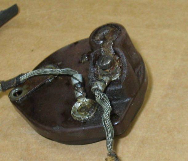 (79.00 KB)
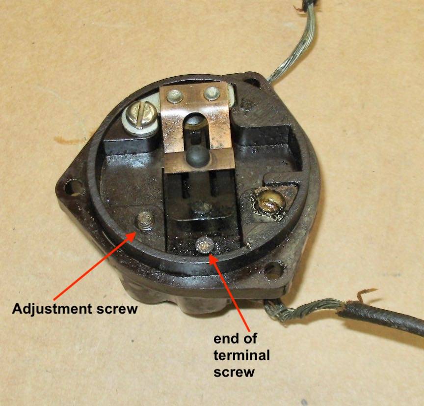
This Post was from: https://packardinfo.com/xoops/html/modules/newbb/viewtopic.php?post_id=210616