Re: 1942 "160" turn signal & brake wiring problem??
Posted by HH56 On 2021/6/4 20:55:34
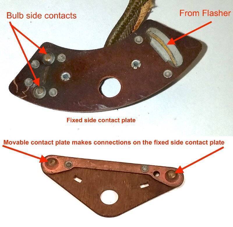
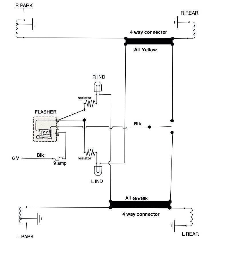
I believe but will not swear to it that the 42 turn signal circuit is identical to the 46 - 7 circuit and similar to the 48. It is hard to tell from the 42 diagram but if you have two bulbs in the rear, a dual filament for brakes and tail lights and a separate bulb for turn signals, then it will be. If that is the case here is an extraction of the postwar turn signal circuit and a photo of the 46-7 switch showing the contacts. I believe the 42 switch will be the same electrically although maybe slightly different physically to fit a different shroud.
Potential issues are a dirty switch, sockets, any grounds and inline connectors. Packards seem to be very prone to poor grounds developing at the park and tail light housings and that does seriously affect the various bulbs with results from no action at all to very erratic operation. The old thermal flashers are very dependent upon the correct resistance thru the wiring, bulb filaments to ground. That would be the first suggestion is ensure all the bolts or studs from housings that connect to sheetmetal and provide the grounds are clean and tight. Sockets that get wet can also have the phenolic plate that supports the contacts warp and develope a poor connection. The inline connectors -- particularly those exposed to any moisture -- were known to oxidize even in Packards day so they could also be a source of high resistance and low voltage.
Circuit function: When switch is moved it connects bulbs from the R or L side to the flasher to start the heater and activate the bimetal for the flash cycle. When the bimetal makes contact flasher provides 6v output at L and at the same time both indicator lights get power thru a resistor from the contact which is activated like a relay and connected to P. Note that the indicator lights have their other wire connected to the opposite side signal bulbs. This is to have the ground for the indicator bulbs be provided by going to ground thru the inactive filaments on the off side so only one indicator light is on at a time. As soon as the bimetal makes the solid connection it effectively bypasses the heater by providing the same voltage to both sides. This results in the heater cooling and as it cools the bimetal unbends to stop the voltage and action to extinguish the lights. Since the signal switch is still connected the heater starts again and cycle repeats until the switch is turned off.
Attach file:
 41-48 turn signal sw3.jpg (251.05 KB)
46-7 turn signal extraction.jpg (55.62 KB)
Potential issues are a dirty switch, sockets, any grounds and inline connectors. Packards seem to be very prone to poor grounds developing at the park and tail light housings and that does seriously affect the various bulbs with results from no action at all to very erratic operation. The old thermal flashers are very dependent upon the correct resistance thru the wiring, bulb filaments to ground. That would be the first suggestion is ensure all the bolts or studs from housings that connect to sheetmetal and provide the grounds are clean and tight. Sockets that get wet can also have the phenolic plate that supports the contacts warp and develope a poor connection. The inline connectors -- particularly those exposed to any moisture -- were known to oxidize even in Packards day so they could also be a source of high resistance and low voltage.
Circuit function: When switch is moved it connects bulbs from the R or L side to the flasher to start the heater and activate the bimetal for the flash cycle. When the bimetal makes contact flasher provides 6v output at L and at the same time both indicator lights get power thru a resistor from the contact which is activated like a relay and connected to P. Note that the indicator lights have their other wire connected to the opposite side signal bulbs. This is to have the ground for the indicator bulbs be provided by going to ground thru the inactive filaments on the off side so only one indicator light is on at a time. As soon as the bimetal makes the solid connection it effectively bypasses the heater by providing the same voltage to both sides. This results in the heater cooling and as it cools the bimetal unbends to stop the voltage and action to extinguish the lights. Since the signal switch is still connected the heater starts again and cycle repeats until the switch is turned off.
Attach file:
41-48 turn signal sw3.jpg (251.05 KB)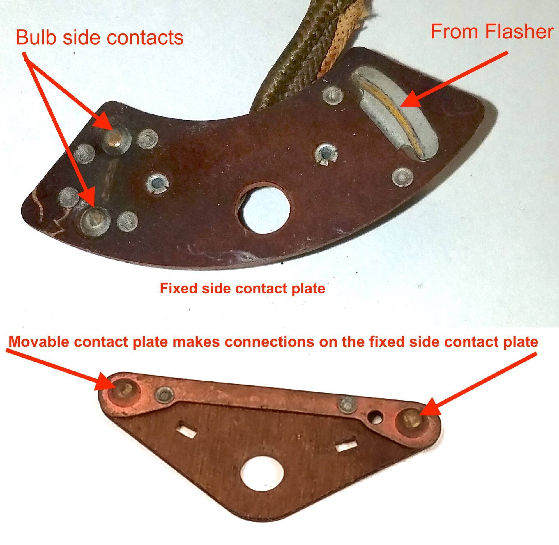 46-7 turn signal extraction.jpg (55.62 KB)
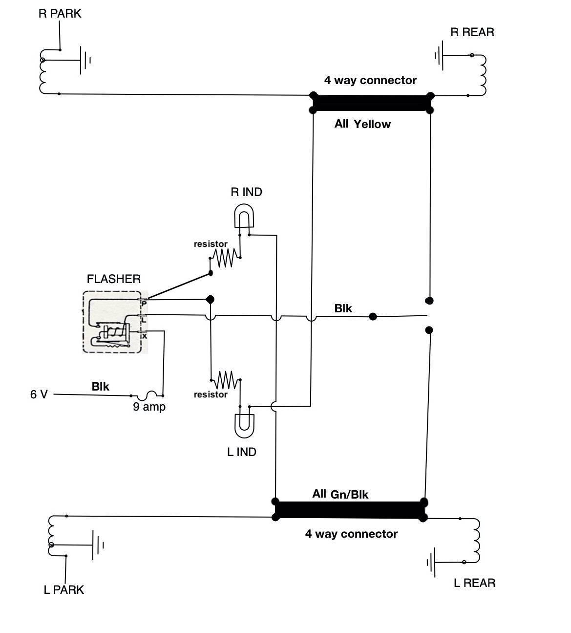
This Post was from: https://packardinfo.com/xoops/html/modules/newbb/viewtopic.php?post_id=234082