Re: 1936 Super Eight timing
Posted by LOL On 2022/8/2 21:07:31
Regarding the synchronization of the dual points, here's what I do.
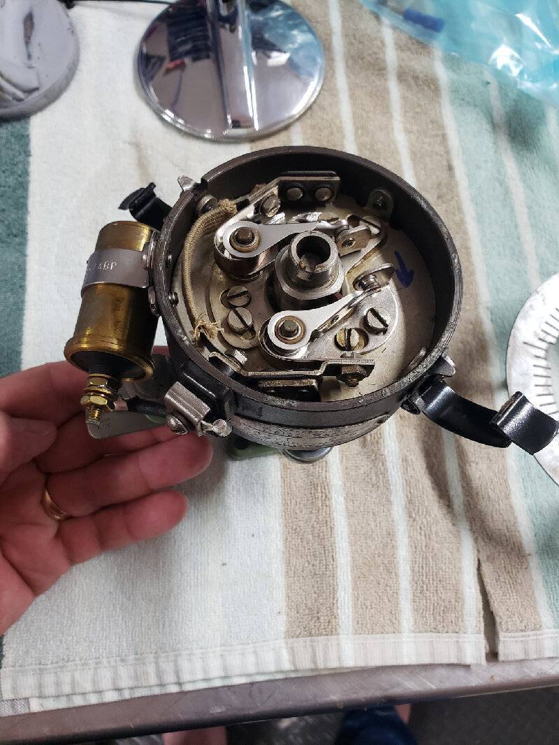
The 1st picture is my distributor (std 8, 14 series).
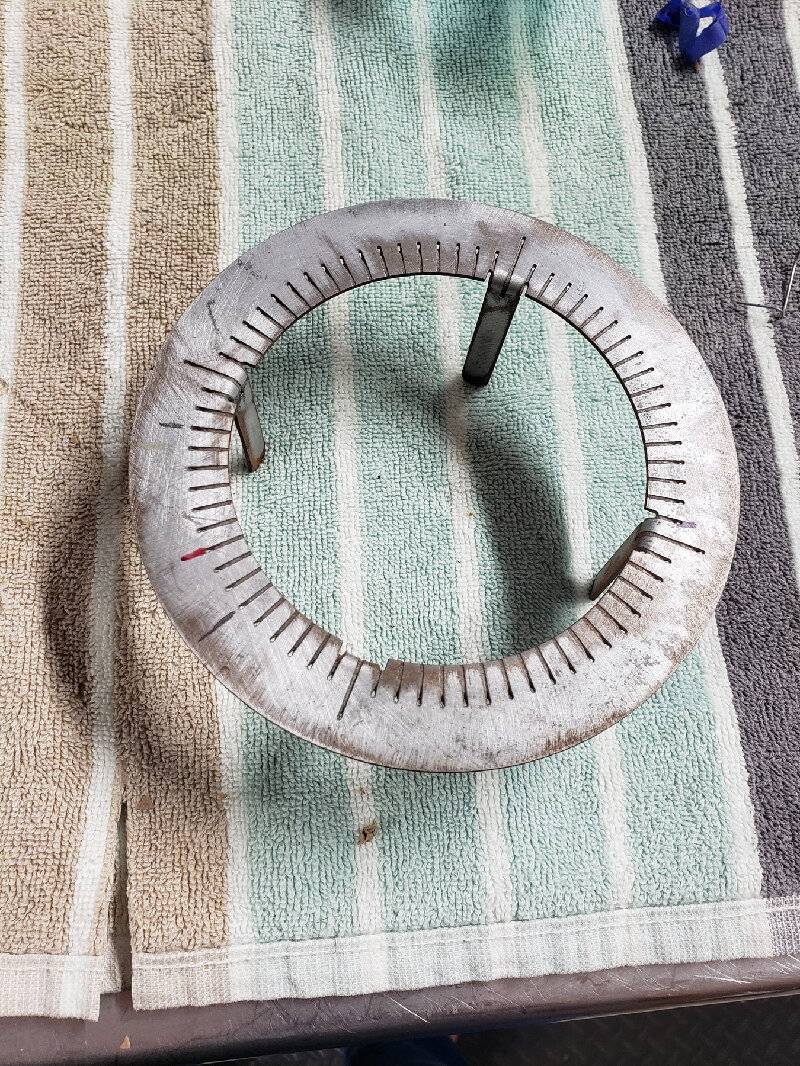
The 2nd picture is a plate I made which fits snugly around the distributor housing and is marked at 5 degree increments.
The 3rd picture is an old rotor onto which I attached a paperclip which I bent to use as an indicator on the plate in picture 2.
The 4th picture is everything assembled and ready to test.
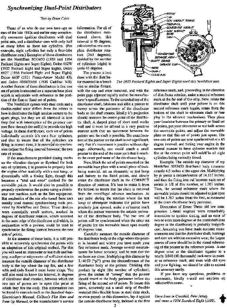
The procedure is as follows (and I summarized and adapted it from an article by Dave Czirr which I have also attached).
1. Remove the distributor from the engine as this is easier done on a bench
2. Place the incremented plate around the distributor.
--- If you don't have a plate and chances are you don't, I sell them so feel free to get in touch 618-304-0907 or whiteglove@mail.com ---
3. Place the rotor on the distributor making sure the paperclip moves smoothly on top of the incremented plate.
4. Block the points on the MOVABLE plate by placing a small piece of electrical tape between the contact surfaces.
5. Connect an Ohm meter to the STATIONARY points and rotate the rotor in the CORRECT direction until the points open.
6. Make a mark on the incremented plate.
7. Remove the tape from the points in step 4 and apply it to the STATIONARY points.
8. Connect the Ohm meter to the MOVABLE points and rotate in the CORRECT direction until the points open.
9. Make a mark on the incremented plate
The two marks should be 45 degrees apart for the points to be synchronized (360 degrees divided by 8 cylinders).
If the marks are not 45 degrees apart, adjust the MOVABLE plate to increase or decrease the angular distance where the points open.
Repeat as necessary until the 45 degree separation is achieved.
Attach file:
 20220802_212431.jpg (265.53 KB)
20220802_212436.jpg (608.28 KB)
20220802_212448.jpg (441.63 KB)

20220802_212535.jpg (353.01 KB)

Synchronizing Dual Points.jpg (424.43 KB)
The 1st picture is my distributor (std 8, 14 series).
The 2nd picture is a plate I made which fits snugly around the distributor housing and is marked at 5 degree increments.
The 3rd picture is an old rotor onto which I attached a paperclip which I bent to use as an indicator on the plate in picture 2.
The 4th picture is everything assembled and ready to test.
The procedure is as follows (and I summarized and adapted it from an article by Dave Czirr which I have also attached).
1. Remove the distributor from the engine as this is easier done on a bench
2. Place the incremented plate around the distributor.
--- If you don't have a plate and chances are you don't, I sell them so feel free to get in touch 618-304-0907 or whiteglove@mail.com ---
3. Place the rotor on the distributor making sure the paperclip moves smoothly on top of the incremented plate.
4. Block the points on the MOVABLE plate by placing a small piece of electrical tape between the contact surfaces.
5. Connect an Ohm meter to the STATIONARY points and rotate the rotor in the CORRECT direction until the points open.
6. Make a mark on the incremented plate.
7. Remove the tape from the points in step 4 and apply it to the STATIONARY points.
8. Connect the Ohm meter to the MOVABLE points and rotate in the CORRECT direction until the points open.
9. Make a mark on the incremented plate
The two marks should be 45 degrees apart for the points to be synchronized (360 degrees divided by 8 cylinders).
If the marks are not 45 degrees apart, adjust the MOVABLE plate to increase or decrease the angular distance where the points open.
Repeat as necessary until the 45 degree separation is achieved.
Attach file:
20220802_212431.jpg (265.53 KB) 20220802_212436.jpg (608.28 KB)
 20220802_212448.jpg (441.63 KB)
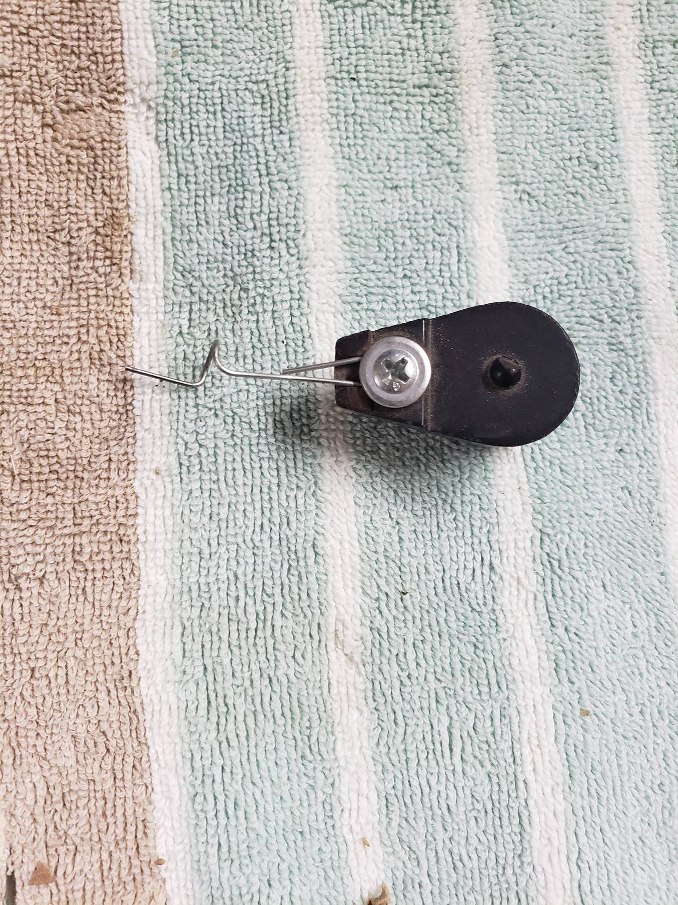 20220802_212535.jpg (353.01 KB)
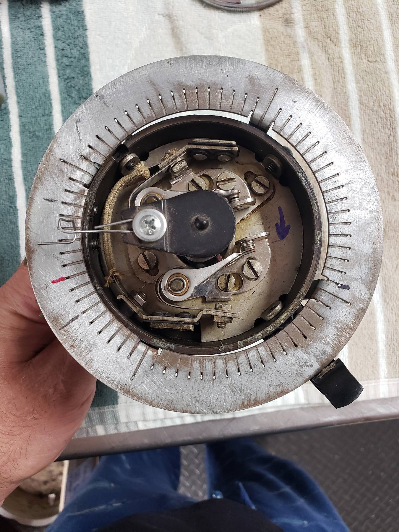 Synchronizing Dual Points.jpg (424.43 KB)
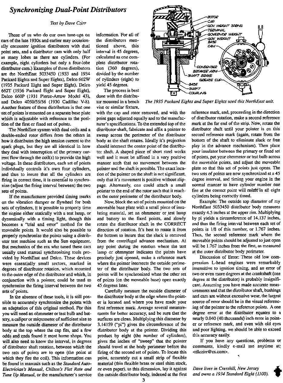
This Post was from: https://packardinfo.com/xoops/html/modules/newbb/viewtopic.php?post_id=246700