Re: Stewart's 1955 Packard 400
Posted by Stewart Ballard On 2023/9/2 19:37:09
Here is how I created the adapter plate for the Dorman PW motor to my Packard regulator.
I am not smart enough to provide a detailed blueprint /diagram of hole placement and measurements but will do my best to show you how I got this done.
I used some scrape ⅛” plate metal that I had left from another project.
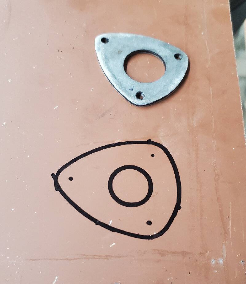
Then I used one of the “egg” shaped, rubber bushings from the original motor and traced its shape onto the metal plate. That gave me the center hole and the 3 holes to mount it to the window regulator (Adapter1.jpg).
Again have the regulator lying nearby so you can keep up with the orientation of the motor. It's easy to get turned around.
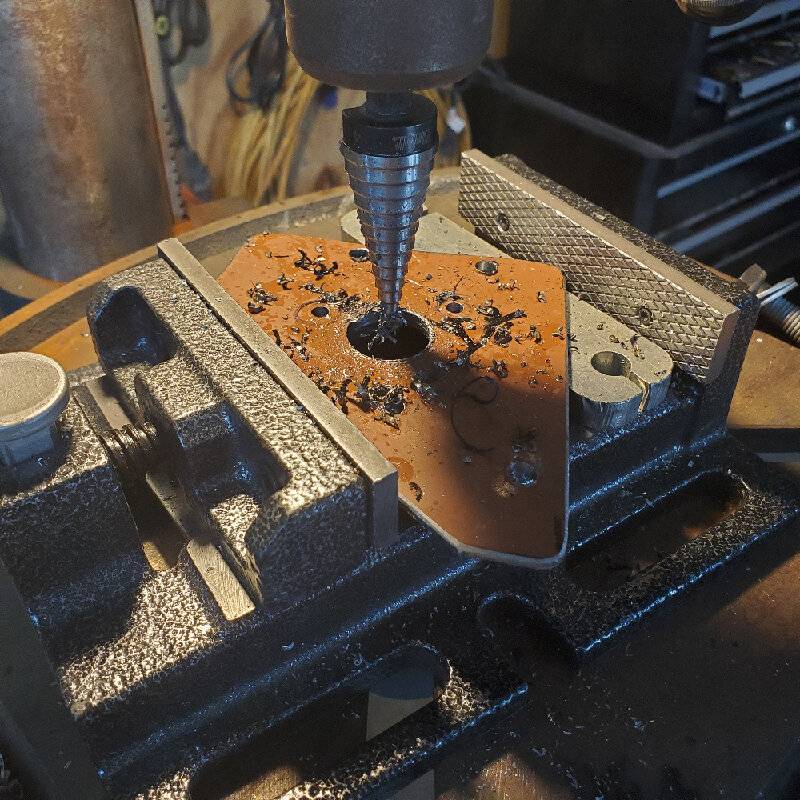
Another hint is getting the shaft of the new motor aligned over the center hole so you can mark the location of the three holes that will be used to attach the motor to the adapter plate. First, I drilled those first 3 mount holes out to ¼. I then drilled the center hole just large enough so that the new gear/shaft of the new motor fits through it, about ½” (adapter2.jpg). I’ll drill the center hole out more later but for now, I need it smaller.
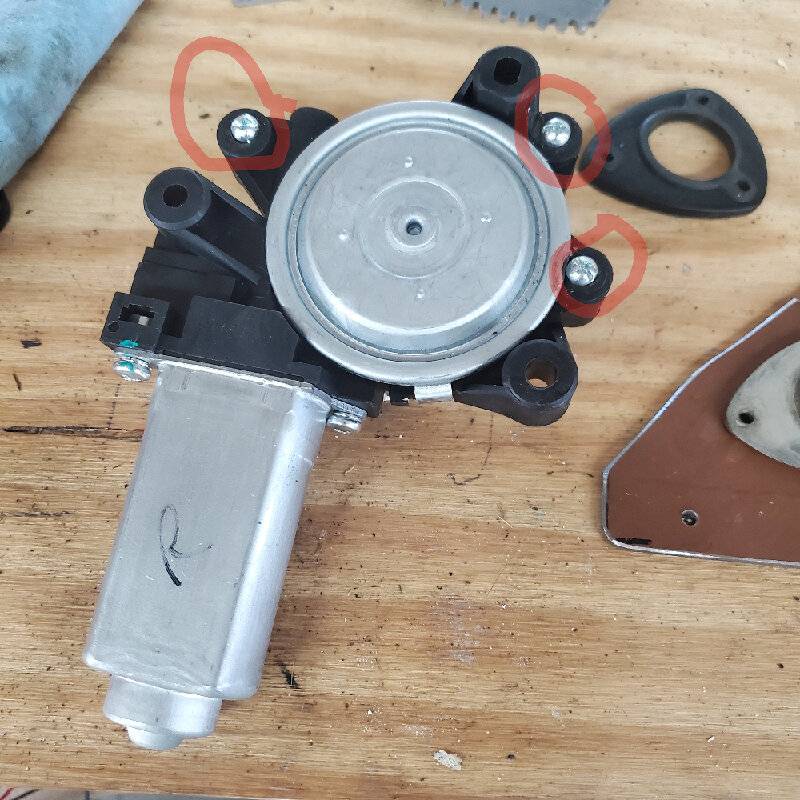
Once those first 4 holes are drilled, I put the gear/shaft of the motor through the center hole and use a scribe to mark the 3 holes for mounting the motor. Sidetwo.jpg shows the 3 holes that I used to mount the motor to the adapter. There are 6 mount holes on the motor itself but I only used the 3 lower holes, shown in the image.
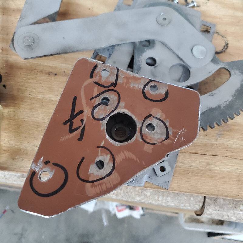
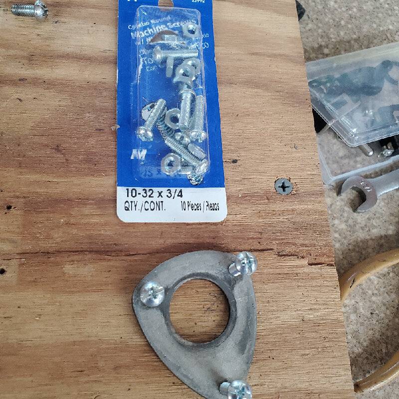
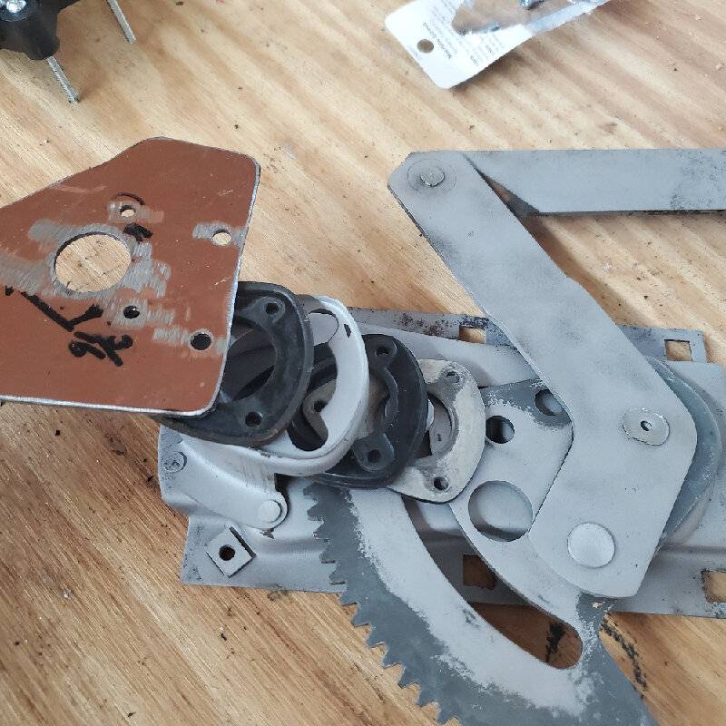
Now I drilled those 3 holes out to ¼” as well. I also enlarged the center hole out to ⅞” (adapter4.jpg). I use ¾” - #10 screws to attach the adapter plate to the regulator (adapter6.jpg). I tried to show how I used some of the original parts in the mounting (adapter5.jpg).
Now the motor is ready to mount on the adapter.
For those of you that cannot wait the last photo is for you. It shows the adapter that I am using to tie it all together(coupling1.jpg). I’ll explain that in the next post.
The only special tool that I use in this whole project is a drill press.
I am sure I have forgotten something. If so, I’ll pick it up in a later post.
Attach file:
 Adapter1.jpg (49.38 KB)
Adapter2.jpg (136.11 KB)
SideTwo.jpg (103.57 KB)
adapter4.jpg (72.11 KB)
adapter6.jpg (156.22 KB)
adapter5.jpg (96.43 KB)
coupling1.jpg (79.02 KB)

I am not smart enough to provide a detailed blueprint /diagram of hole placement and measurements but will do my best to show you how I got this done.
I used some scrape ⅛” plate metal that I had left from another project.
Then I used one of the “egg” shaped, rubber bushings from the original motor and traced its shape onto the metal plate. That gave me the center hole and the 3 holes to mount it to the window regulator (Adapter1.jpg).
Again have the regulator lying nearby so you can keep up with the orientation of the motor. It's easy to get turned around.
Another hint is getting the shaft of the new motor aligned over the center hole so you can mark the location of the three holes that will be used to attach the motor to the adapter plate. First, I drilled those first 3 mount holes out to ¼. I then drilled the center hole just large enough so that the new gear/shaft of the new motor fits through it, about ½” (adapter2.jpg). I’ll drill the center hole out more later but for now, I need it smaller.
Once those first 4 holes are drilled, I put the gear/shaft of the motor through the center hole and use a scribe to mark the 3 holes for mounting the motor. Sidetwo.jpg shows the 3 holes that I used to mount the motor to the adapter. There are 6 mount holes on the motor itself but I only used the 3 lower holes, shown in the image.
Now I drilled those 3 holes out to ¼” as well. I also enlarged the center hole out to ⅞” (adapter4.jpg). I use ¾” - #10 screws to attach the adapter plate to the regulator (adapter6.jpg). I tried to show how I used some of the original parts in the mounting (adapter5.jpg).
Now the motor is ready to mount on the adapter.
For those of you that cannot wait the last photo is for you. It shows the adapter that I am using to tie it all together(coupling1.jpg). I’ll explain that in the next post.
The only special tool that I use in this whole project is a drill press.
I am sure I have forgotten something. If so, I’ll pick it up in a later post.
Attach file:
Adapter1.jpg (49.38 KB) Adapter2.jpg (136.11 KB)
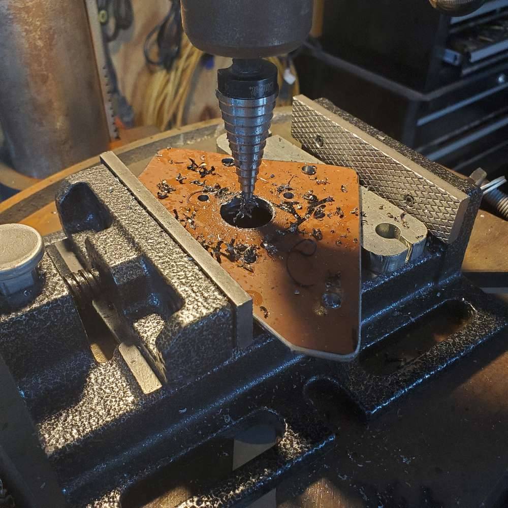 SideTwo.jpg (103.57 KB)
 adapter4.jpg (72.11 KB)
 adapter6.jpg (156.22 KB)
 adapter5.jpg (96.43 KB)
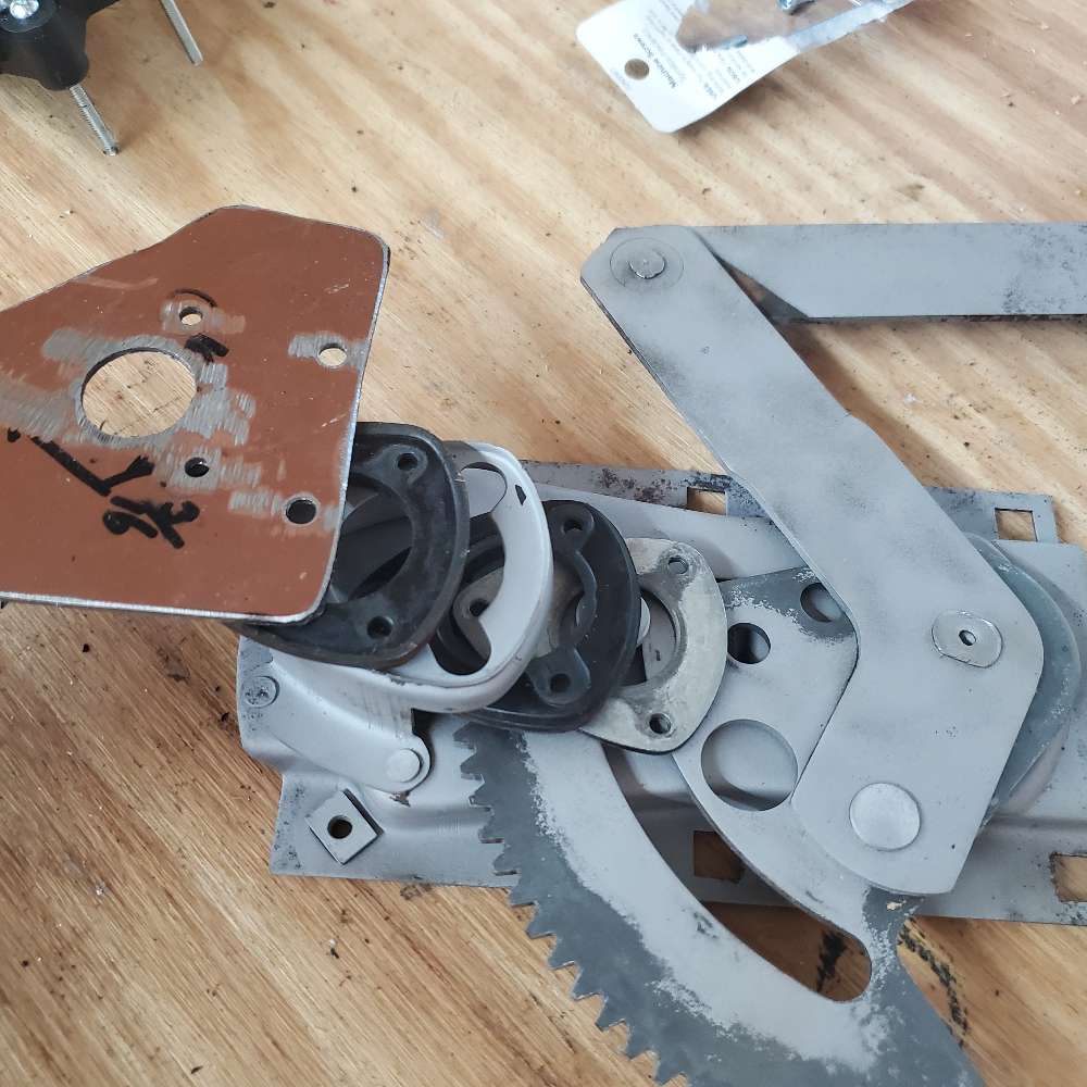 coupling1.jpg (79.02 KB)
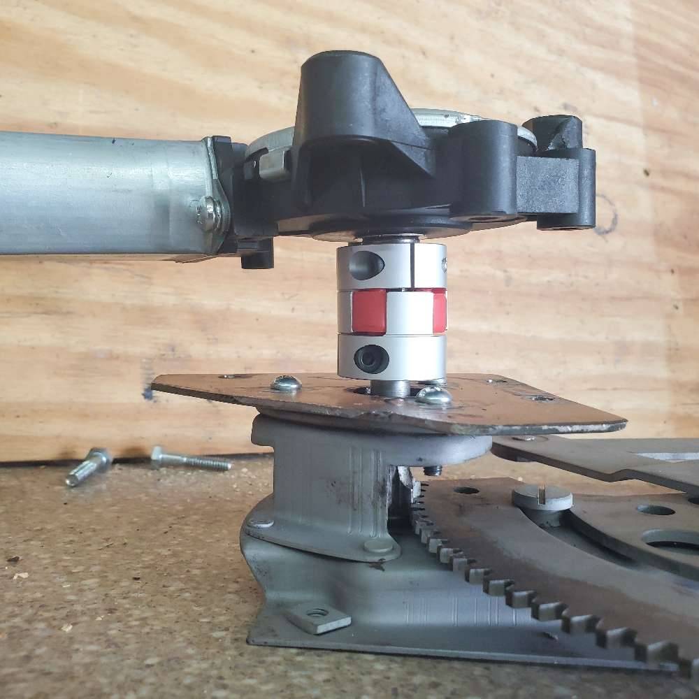
This Post was from: https://packardinfo.com/xoops/html/modules/newbb/viewtopic.php?post_id=261097