Re: Vacation Car - 56 Patrician
Posted by HH56 On 2023/4/18 10:42:37
You might want to do a bit more research on what else will be needed in the circuit when using the 555 as the TL timer solution. As I recall, the 555 is somewhat sensitive and needs a fairly clean power supply or else operation becomes very erratic or chip doesn't work at all.
Auto electrical systems of that era are inherently "noisy" because of all the switches, coil and other ignition components, and even the generator brushes sparking. That activity is broadcast or directly connected to the same wiring used for voltage distribution so is picked up and carried all over. Evidence that by the various filter capacitors that need to be added at specific places to keep most of the electrical "noise" from being picked up and becoming static on the radio. You would probably need to add some conditioning directly to the power going into the chip.
Also, in that diagram the the load is shown as only being an LED which typically needs on average about 10ma to work. I don't know offhand how much current the 555 can directly power but depending on the relay used, you will probably need to have the timer chip trigger a transistor stage with the transistor being capable of carrying the current needed for the relay coil. The transistor stage will require a few components and the relay coil might also need conditioning so the back emf when the magnetic field collapses is not sent back to the transistor and damages it.
I went ahead and ordered a couple of stand alone timer relays that MIGHT work. Won't know for sure until they get here which should be tomorrow. If you can hold off a few days until I can test them it may be an easier solution. If they don't work then you can go to Riki's friend and see if he will make you a proper circuit assy or back to researching the 555 timer with only a bit of time wasted.
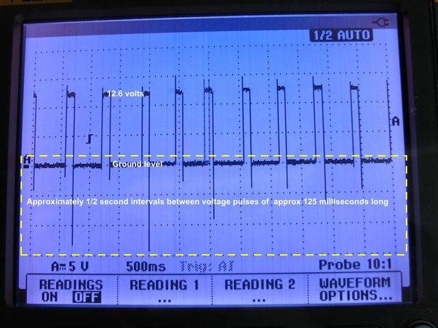
For anyone interested, here is an example of what is meant by electrical noise as shown on an oscilloscope. The heavy center dark line is ground, the heavy line at the top of the square pulses is 12v. On a clean power supply those lines would be extremely straight and much narrower. Notice the roughness in these lines along with the small spikes above the 12v line and the very large ones in the dashed box below the ground line. That is noise and in this case is caused only by the instrument voltage regulator contacts operating. Imagine what all the other switches could do when added to what is from only one component. Solid state circuitry can not work with that kind of activity on the power supply so various means of conditioning input voltage is required..
Attach file:
 Instrument Regulator output waveform.jpg (48.83 KB)

Auto electrical systems of that era are inherently "noisy" because of all the switches, coil and other ignition components, and even the generator brushes sparking. That activity is broadcast or directly connected to the same wiring used for voltage distribution so is picked up and carried all over. Evidence that by the various filter capacitors that need to be added at specific places to keep most of the electrical "noise" from being picked up and becoming static on the radio. You would probably need to add some conditioning directly to the power going into the chip.
Also, in that diagram the the load is shown as only being an LED which typically needs on average about 10ma to work. I don't know offhand how much current the 555 can directly power but depending on the relay used, you will probably need to have the timer chip trigger a transistor stage with the transistor being capable of carrying the current needed for the relay coil. The transistor stage will require a few components and the relay coil might also need conditioning so the back emf when the magnetic field collapses is not sent back to the transistor and damages it.
I went ahead and ordered a couple of stand alone timer relays that MIGHT work. Won't know for sure until they get here which should be tomorrow. If you can hold off a few days until I can test them it may be an easier solution. If they don't work then you can go to Riki's friend and see if he will make you a proper circuit assy or back to researching the 555 timer with only a bit of time wasted.
For anyone interested, here is an example of what is meant by electrical noise as shown on an oscilloscope. The heavy center dark line is ground, the heavy line at the top of the square pulses is 12v. On a clean power supply those lines would be extremely straight and much narrower. Notice the roughness in these lines along with the small spikes above the 12v line and the very large ones in the dashed box below the ground line. That is noise and in this case is caused only by the instrument voltage regulator contacts operating. Imagine what all the other switches could do when added to what is from only one component. Solid state circuitry can not work with that kind of activity on the power supply so various means of conditioning input voltage is required..
Attach file:
 Instrument Regulator output waveform.jpg (48.83 KB)
This Post was from: https://packardinfo.com/xoops/html/modules/newbb/viewtopic.php?post_id=255981