Re: 1956 Patrican revival.
Posted by HH56 On 2022/8/3 22:38:29
The ignition switch is the standard 4 terminal electrical design but the switch itself is unique to Packard in the way it mounts to the dash bezel. The switches and bezels are starting to get hard to find and expensive but if you want to stay stock and need a new switch finding an original type will be the option.
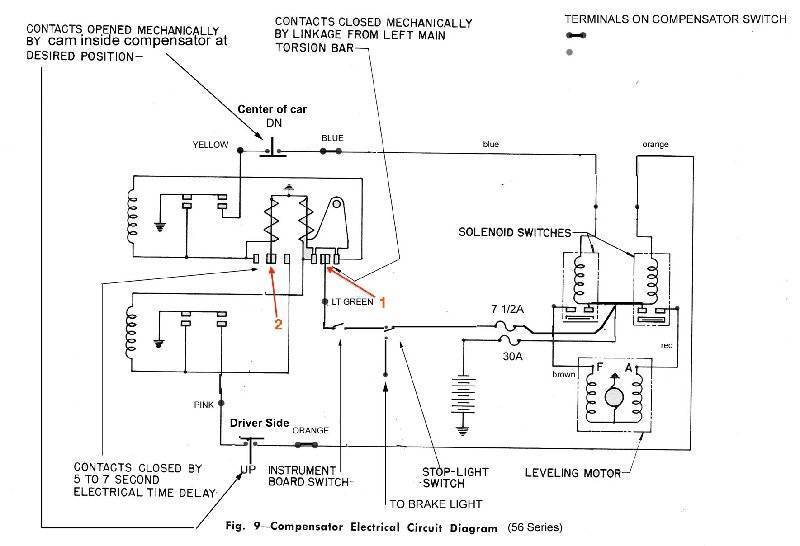
There are two inline fuses for the torsion level circuit connected to the solenoids in the space next to the cowl under the left fender. The 30 amp is for the entire system and a 7 1/2 amp which is fed off the 30 is for the brake lights and torsion level control switch. If you have power on the purple wire at the brake switch located on the frame rail under the battery and vent tube then when brakes are relaxed check to see if there is voltage going out on the light green wire which feeds the under dash switch and control switch. The original 3 terminal brake switch is a known failure item and frequently the cause of no TL. If you are getting voltage out then assuming the dash switch and wiring to control switch is good the problem could be oxidized contacts in the control switch.
The windows are fed voltage straight from the battery terminal at the starter solenoid via a red wire which goes thru a circuit breaker to a relay located on the engine side of cowl ledge in front of the driver. When the ign key is turned on the relay is energized to supply power to the window switches. If all windows and switches are inoperative I would first look to see if voltage is present and the relay is turning on. On a Patrician there may be a second relay in that location also fed off the window circuit breaker. It is for the optional electric door locks if those were installed. The relays look the same but are different electrically.
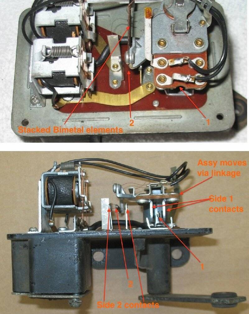
The window and door lock diagram is in the service manual but here is a complete drawing of the TL circuit showing all the relay and switch contacts not seen in the TL wiring diagram in the service manual. The drawing needs a touchup though because of the way the two limit switches could be interpreted. They are in fact both normally closed. The red 1 and 2 refer to the contacts in the photo of a control switch. If you have voltage on the light green wire at the switch I would use a contact burnisher and CAREFULLY clean all contacts in the switch including the relays. Pay attention the burnisher does not catch or damage one of the thin wires to the bimetal heaters when doing contacts 2. If the switch has never been opened you will need to drill out the rivets to remove the cover. Replace with small screws and nuts. If cleaning does not cure the issue then more troubleshooting will be needed.
Attach file:
 56TorSwitch1.jpg (130.47 KB)
TL switch contacts.jpg (148.12 KB)
There are two inline fuses for the torsion level circuit connected to the solenoids in the space next to the cowl under the left fender. The 30 amp is for the entire system and a 7 1/2 amp which is fed off the 30 is for the brake lights and torsion level control switch. If you have power on the purple wire at the brake switch located on the frame rail under the battery and vent tube then when brakes are relaxed check to see if there is voltage going out on the light green wire which feeds the under dash switch and control switch. The original 3 terminal brake switch is a known failure item and frequently the cause of no TL. If you are getting voltage out then assuming the dash switch and wiring to control switch is good the problem could be oxidized contacts in the control switch.
The windows are fed voltage straight from the battery terminal at the starter solenoid via a red wire which goes thru a circuit breaker to a relay located on the engine side of cowl ledge in front of the driver. When the ign key is turned on the relay is energized to supply power to the window switches. If all windows and switches are inoperative I would first look to see if voltage is present and the relay is turning on. On a Patrician there may be a second relay in that location also fed off the window circuit breaker. It is for the optional electric door locks if those were installed. The relays look the same but are different electrically.
The window and door lock diagram is in the service manual but here is a complete drawing of the TL circuit showing all the relay and switch contacts not seen in the TL wiring diagram in the service manual. The drawing needs a touchup though because of the way the two limit switches could be interpreted. They are in fact both normally closed. The red 1 and 2 refer to the contacts in the photo of a control switch. If you have voltage on the light green wire at the switch I would use a contact burnisher and CAREFULLY clean all contacts in the switch including the relays. Pay attention the burnisher does not catch or damage one of the thin wires to the bimetal heaters when doing contacts 2. If the switch has never been opened you will need to drill out the rivets to remove the cover. Replace with small screws and nuts. If cleaning does not cure the issue then more troubleshooting will be needed.
Attach file:
56TorSwitch1.jpg (130.47 KB)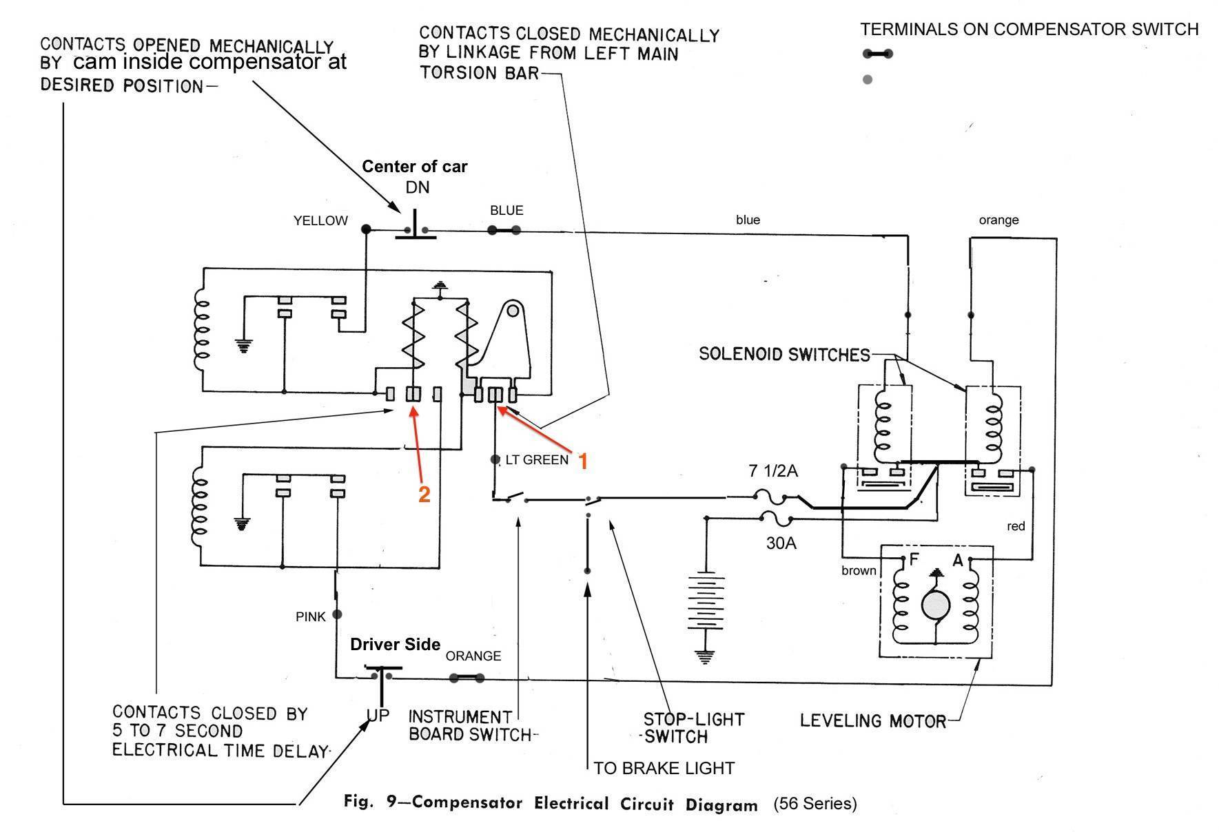 TL switch contacts.jpg (148.12 KB)
This Post was from: https://packardinfo.com/xoops/html/modules/newbb/viewtopic.php?post_id=246724