Re: Snapey's 1935 Racing Biposto
Posted by Matt snape On 2011/7/4 6:43:45
So, last weekend was busy with other things happening, but I did get to spend some very productive time on the Biposto project between everything else.
The goal was to clean up (read remove as much weight as possible from) the rear of the chassis, establish a good solid centre line standard for measuring and then start the chassis modifications with narrowing the rear end.
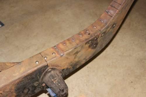
In standard form the distance across the rear of the chassis is about 45" with the chassis rails essentially tapering uniformly from rear to front where they measure about 28.5" (as you can see in some of the earlier photos). My objective was to cut the chassis C-section flanges top and bottom starting from just behind the end of the crucifix on each side and then pull the rails inwards a little at a time. I did some basic calculations which showed that with a cut of about 1/16" I should be able to get about 1.5-1" movement inwards for each rail. These calcs told me that I would probably need around 10 cuts to do the job and looking at the chassis I decided to make them at 2" intervals.
I even went so far to draw up the curve that would be produced and plotted it out at full 1:1 scale - the piece of paper is over 7ft long! The curve looked great so we proceeded with the plans of a 1/16" cut every 2". The drawing I made could also be used to guide the curve if needed, but this didn't end up being required.
By the way - just to let you know that I do most of my work in millimetres, but most people understand inches and my father reckoned it was only fitting to use imperial measurements when dealing with "a big Yankee truck" (his words, not mine!) like the '34.
So all the rivets were ground, drilled and punched out (a big job in itself) and the two rear cross members removed along with the forged steel spring hanger eyes. These steel forgings will most likely be recycled and used on the front of the car, where their different offset should work well to counteract the 'widening' of the hanging points when the tapered chassis rails are cut about 15" shorter at the front. Removal of the cross members left space for putting though a centre beam to give me something to measure off, so 2 pieces of 2x1" RHS were welded across the top of the chassis to fix this to. A length of 1" aluminium square section was then clamped to these to mark the centreline of the car so I could measure off it as the modification progressed. This would get in the way a bit but was the only way to make the changes accurately.
The first cut, as you can see in the first 2 photos, was made right next to the ends of the crucifix. I made this using a wider 1/8" disc in the little 4" grinder, but this proved excessive and just made more work when it came to welding, but it did allow me to take a bit bigger bite to start the process, so the initial change to each rail was more like 2" each side (4" overall). A length of threaded rod was pushed through two existing holes on opposite sides of the chassis and this with a couple of nuts and washers was used to pull and hold the chassis rails in as the work progressed.
1-Cut top and bottom flanges on both sides, 2-pull in, 3-measure, 4-adjust, 5-measure, 6-measure again, 7-tack weld one side top and bottom, 8-measure, 9-adjust, 10-measure, 11-measure again, 12-tack weld other side top and bottom, 13-then cut again 2" further along and start the process over... 9 times!!!! My back is still sore and I now understand why the professionals spend thousands on chassis jigs and rotisseries!
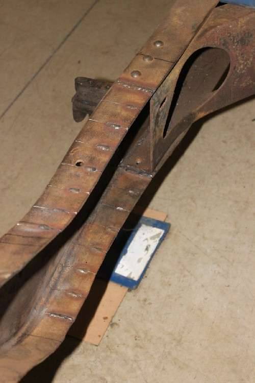
After the first set of cuts I changed to the thin kerf 1mm cutting discs and these really are great things to have around! The cuts are quicker and cleaner and you make less mess by removing less material... hmmm - note to self - must remember to put some more on the shopping list...
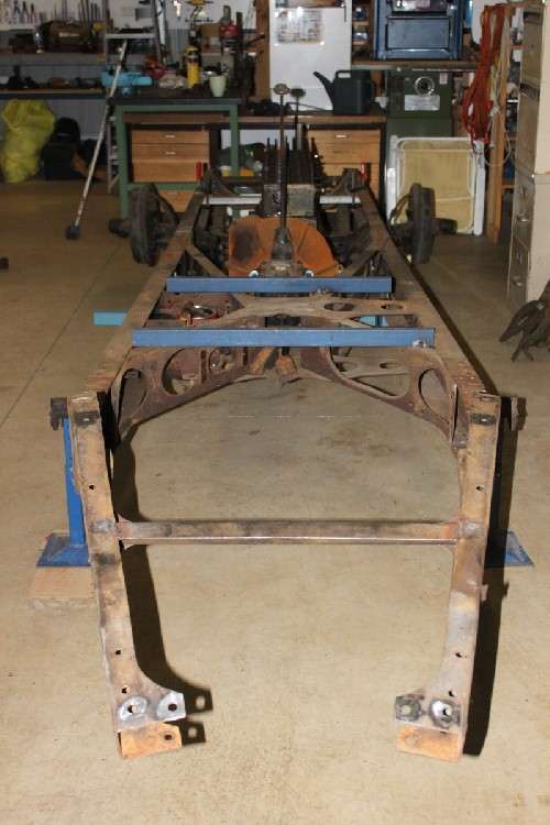
One of the tricks I found that seems to work is taking account of shrinkage after a weld is made. As the weld cools it shrinks and this can (and often does) cause distortion in the job. But measuring before each weld was made I was able to weld the side that needed to move in the most first each time, then adjust the pull on the other side to match it and allow a little for shrinkage there as well and it worked out very well indeed - even if I do say so myself (which - quite obviously - I do). Especially when you consider that yours truly is a rank amateur at these things. The end result of all this is that the width across the rear end of the chassis is now closer to 22" instead of 45" - which is pretty much exactly what I wanted.
Two things surprised me when I first removed the two rear cross members from the chassis rails. The first was how much strain they had been under. When I finally removed the last rivet that was holding it all together the whole thing kinda went 'sproing'! Not enough to throw things in the air, you understand, but enough to make me move my hand out of the way very quickly when I saw it coming. I can only think that since there is no sign of repair to the chassis itself that these forces have been stored in that metal for almost 80years... beat that Mr Eveready! I almost wish I had gained a scar from it so that it did not pass unrecorded - but I suppose that is what I am doing by writing it all down here isn't it?
The second thing that surprised me was just how much ridgity they add to the rear of the chassis. Without these in place I could just tap the end of one chassis rail and it would wobble all over the place. I could grab the end of each rail and twist them 5 or 10 degrees either way just with my hand. Even up and down the amount of movement is quite pronounced, especially given the size & depth of the chassis rails. "Hmmm" I thought to myself... " I will probably need to fix that..."
Keeping the amount of tension or pre-existing distortion in mind then, should I have expected it to be easy to put the first of these two cross members back into position once the cutting and welding of the rails was completed? Probably not, but I did. The rear most piece that joins the very rear ends of the rails together is to be replaced with two lengths of DOM tube which will cantilever the rear ends of the rear spring packs, and it was somewhat out of shape anyway, so it ended up on the 'Jenny Craig Pile'. This is where all the steel removed from the car is being placed so that I can weigh it at the end of the project. The cross member that was second from the rear, which I think the fuel tank would have been strapped to, was then cleaned up with the steel cup brush on the 4" grinder, measured, marked, cut and checked for fit. G clamps and vice grips were used to pull it all back into alignment while it was welded into place. There was some head scratching and grunting involved, but hopefully the energy that I put into it all will go 'sproing' and catch some other poor fool by surprise if they ever decide to cut up my hard work! Given the change in geometry that had taken place this was a little bit tedious, but I'm very happy with the result - an original (but lighter) piece of steel back in close to its original position and serving its original purpose very well. Bit of a shame that no one will ever see it really...
Now some of you may be looking at some of these photos thinking it all looks too narrow to retain the stiffness that would be required, but remember that the car will end up weighing (hopefully) less than half of its original weight and that only a fraction of that will be placed on the rear most spring hangers. Also, to comply with local competition regulations the car will need to be fitted with a roll bar, and I plan to brace this back to the tail and triangulate the structure and so stiffen up the rear of the car substantially.
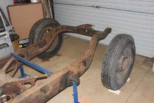
As well as all this I also (with the help of my beautiful and long suffering wife) pulled the rear diff out of the way and placed it on blocks to one side. My next job here will be to use the hydraulic puller that I have borrowed from my father to pop the rear hubs off the axles to examine the rear brakes, seals and bearings. If it all looks OK I will probably just put it back together and see how it goes. I have already removed the front hubs and drums and found that everything seemed to be in very good condition - even the brake shoes look serviceable with plenty of meat on them. Certainly enough for the initial test runs which will be done on a closed race circuit.
Also, I pulled the rear spring packs apart to see what could be made of them. I will certainly need the two new main leaves as previously mentioned, but by using one of the old main leaves to make a new second leaf and then removing, switching and modifying the rest of the pack I might be able to get away with minimal cost. I still have to clean them all up properly though (more work for the little grinder) so we will see what can be done. I will also look at using new packs if I can find something locally that will fit. Once again I will leave that up to my local spring guys - they are very good at what they do.
Finally, on Sunday, I jacked up the front of the car and placed jack stands under the chassis in preparation of removal of the front axle and then cutting off the front of the chassis rails. I then poured myself a large glass of red wine and sat and looked at it for a while. This next part is going to be a pretty big job, as putting the front spring points where they will be required is going to require quite a lot of detailed fabrication work - sounds like fun, don't you think?
Attach file:
 (58.81 KB)
(83.09 KB)
(89.27 KB)

(92.71 KB)
(97.40 KB)
(85.11 KB)

(101.79 KB)
The goal was to clean up (read remove as much weight as possible from) the rear of the chassis, establish a good solid centre line standard for measuring and then start the chassis modifications with narrowing the rear end.
In standard form the distance across the rear of the chassis is about 45" with the chassis rails essentially tapering uniformly from rear to front where they measure about 28.5" (as you can see in some of the earlier photos). My objective was to cut the chassis C-section flanges top and bottom starting from just behind the end of the crucifix on each side and then pull the rails inwards a little at a time. I did some basic calculations which showed that with a cut of about 1/16" I should be able to get about 1.5-1" movement inwards for each rail. These calcs told me that I would probably need around 10 cuts to do the job and looking at the chassis I decided to make them at 2" intervals.
I even went so far to draw up the curve that would be produced and plotted it out at full 1:1 scale - the piece of paper is over 7ft long! The curve looked great so we proceeded with the plans of a 1/16" cut every 2". The drawing I made could also be used to guide the curve if needed, but this didn't end up being required.
By the way - just to let you know that I do most of my work in millimetres, but most people understand inches and my father reckoned it was only fitting to use imperial measurements when dealing with "a big Yankee truck" (his words, not mine!) like the '34.
So all the rivets were ground, drilled and punched out (a big job in itself) and the two rear cross members removed along with the forged steel spring hanger eyes. These steel forgings will most likely be recycled and used on the front of the car, where their different offset should work well to counteract the 'widening' of the hanging points when the tapered chassis rails are cut about 15" shorter at the front. Removal of the cross members left space for putting though a centre beam to give me something to measure off, so 2 pieces of 2x1" RHS were welded across the top of the chassis to fix this to. A length of 1" aluminium square section was then clamped to these to mark the centreline of the car so I could measure off it as the modification progressed. This would get in the way a bit but was the only way to make the changes accurately.
The first cut, as you can see in the first 2 photos, was made right next to the ends of the crucifix. I made this using a wider 1/8" disc in the little 4" grinder, but this proved excessive and just made more work when it came to welding, but it did allow me to take a bit bigger bite to start the process, so the initial change to each rail was more like 2" each side (4" overall). A length of threaded rod was pushed through two existing holes on opposite sides of the chassis and this with a couple of nuts and washers was used to pull and hold the chassis rails in as the work progressed.
1-Cut top and bottom flanges on both sides, 2-pull in, 3-measure, 4-adjust, 5-measure, 6-measure again, 7-tack weld one side top and bottom, 8-measure, 9-adjust, 10-measure, 11-measure again, 12-tack weld other side top and bottom, 13-then cut again 2" further along and start the process over... 9 times!!!! My back is still sore and I now understand why the professionals spend thousands on chassis jigs and rotisseries!
After the first set of cuts I changed to the thin kerf 1mm cutting discs and these really are great things to have around! The cuts are quicker and cleaner and you make less mess by removing less material... hmmm - note to self - must remember to put some more on the shopping list...
One of the tricks I found that seems to work is taking account of shrinkage after a weld is made. As the weld cools it shrinks and this can (and often does) cause distortion in the job. But measuring before each weld was made I was able to weld the side that needed to move in the most first each time, then adjust the pull on the other side to match it and allow a little for shrinkage there as well and it worked out very well indeed - even if I do say so myself (which - quite obviously - I do). Especially when you consider that yours truly is a rank amateur at these things. The end result of all this is that the width across the rear end of the chassis is now closer to 22" instead of 45" - which is pretty much exactly what I wanted.
Two things surprised me when I first removed the two rear cross members from the chassis rails. The first was how much strain they had been under. When I finally removed the last rivet that was holding it all together the whole thing kinda went 'sproing'! Not enough to throw things in the air, you understand, but enough to make me move my hand out of the way very quickly when I saw it coming. I can only think that since there is no sign of repair to the chassis itself that these forces have been stored in that metal for almost 80years... beat that Mr Eveready! I almost wish I had gained a scar from it so that it did not pass unrecorded - but I suppose that is what I am doing by writing it all down here isn't it?
The second thing that surprised me was just how much ridgity they add to the rear of the chassis. Without these in place I could just tap the end of one chassis rail and it would wobble all over the place. I could grab the end of each rail and twist them 5 or 10 degrees either way just with my hand. Even up and down the amount of movement is quite pronounced, especially given the size & depth of the chassis rails. "Hmmm" I thought to myself... " I will probably need to fix that..."
Keeping the amount of tension or pre-existing distortion in mind then, should I have expected it to be easy to put the first of these two cross members back into position once the cutting and welding of the rails was completed? Probably not, but I did. The rear most piece that joins the very rear ends of the rails together is to be replaced with two lengths of DOM tube which will cantilever the rear ends of the rear spring packs, and it was somewhat out of shape anyway, so it ended up on the 'Jenny Craig Pile'. This is where all the steel removed from the car is being placed so that I can weigh it at the end of the project. The cross member that was second from the rear, which I think the fuel tank would have been strapped to, was then cleaned up with the steel cup brush on the 4" grinder, measured, marked, cut and checked for fit. G clamps and vice grips were used to pull it all back into alignment while it was welded into place. There was some head scratching and grunting involved, but hopefully the energy that I put into it all will go 'sproing' and catch some other poor fool by surprise if they ever decide to cut up my hard work! Given the change in geometry that had taken place this was a little bit tedious, but I'm very happy with the result - an original (but lighter) piece of steel back in close to its original position and serving its original purpose very well. Bit of a shame that no one will ever see it really...
Now some of you may be looking at some of these photos thinking it all looks too narrow to retain the stiffness that would be required, but remember that the car will end up weighing (hopefully) less than half of its original weight and that only a fraction of that will be placed on the rear most spring hangers. Also, to comply with local competition regulations the car will need to be fitted with a roll bar, and I plan to brace this back to the tail and triangulate the structure and so stiffen up the rear of the car substantially.
As well as all this I also (with the help of my beautiful and long suffering wife) pulled the rear diff out of the way and placed it on blocks to one side. My next job here will be to use the hydraulic puller that I have borrowed from my father to pop the rear hubs off the axles to examine the rear brakes, seals and bearings. If it all looks OK I will probably just put it back together and see how it goes. I have already removed the front hubs and drums and found that everything seemed to be in very good condition - even the brake shoes look serviceable with plenty of meat on them. Certainly enough for the initial test runs which will be done on a closed race circuit.
Also, I pulled the rear spring packs apart to see what could be made of them. I will certainly need the two new main leaves as previously mentioned, but by using one of the old main leaves to make a new second leaf and then removing, switching and modifying the rest of the pack I might be able to get away with minimal cost. I still have to clean them all up properly though (more work for the little grinder) so we will see what can be done. I will also look at using new packs if I can find something locally that will fit. Once again I will leave that up to my local spring guys - they are very good at what they do.
Finally, on Sunday, I jacked up the front of the car and placed jack stands under the chassis in preparation of removal of the front axle and then cutting off the front of the chassis rails. I then poured myself a large glass of red wine and sat and looked at it for a while. This next part is going to be a pretty big job, as putting the front spring points where they will be required is going to require quite a lot of detailed fabrication work - sounds like fun, don't you think?
Attach file:
(58.81 KB)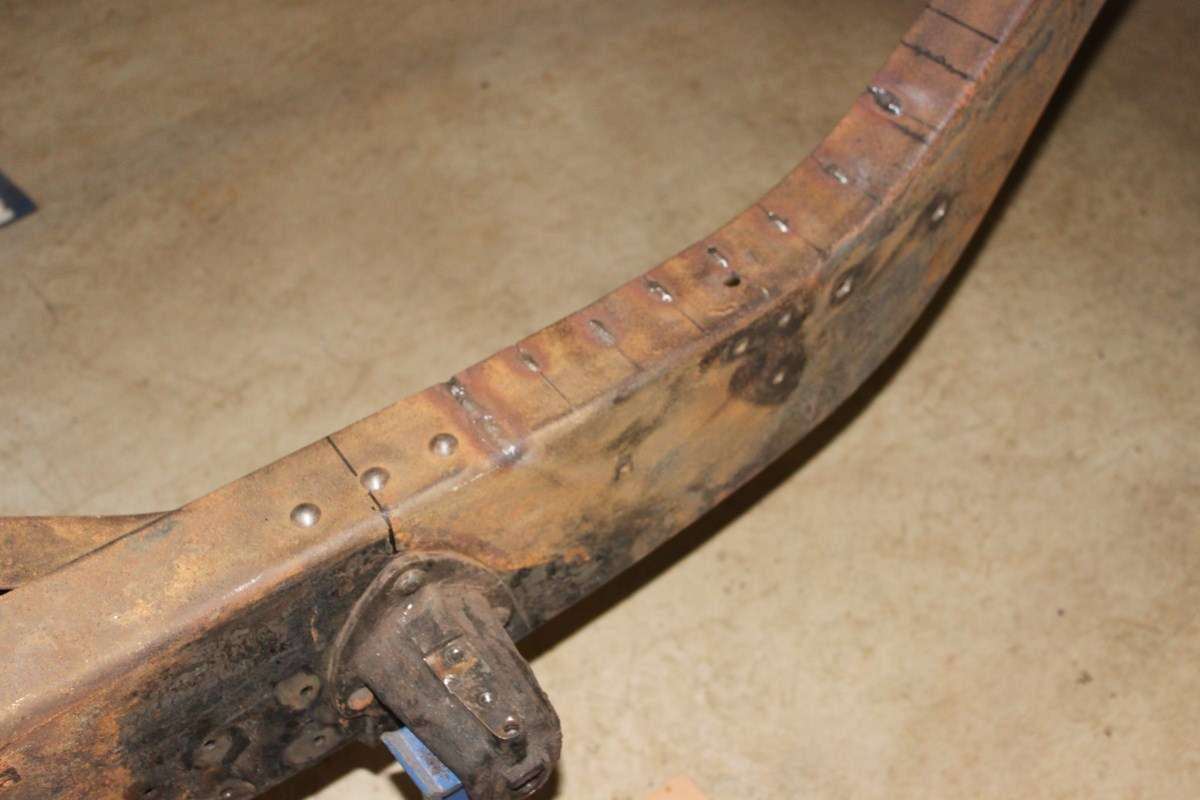 (83.09 KB)
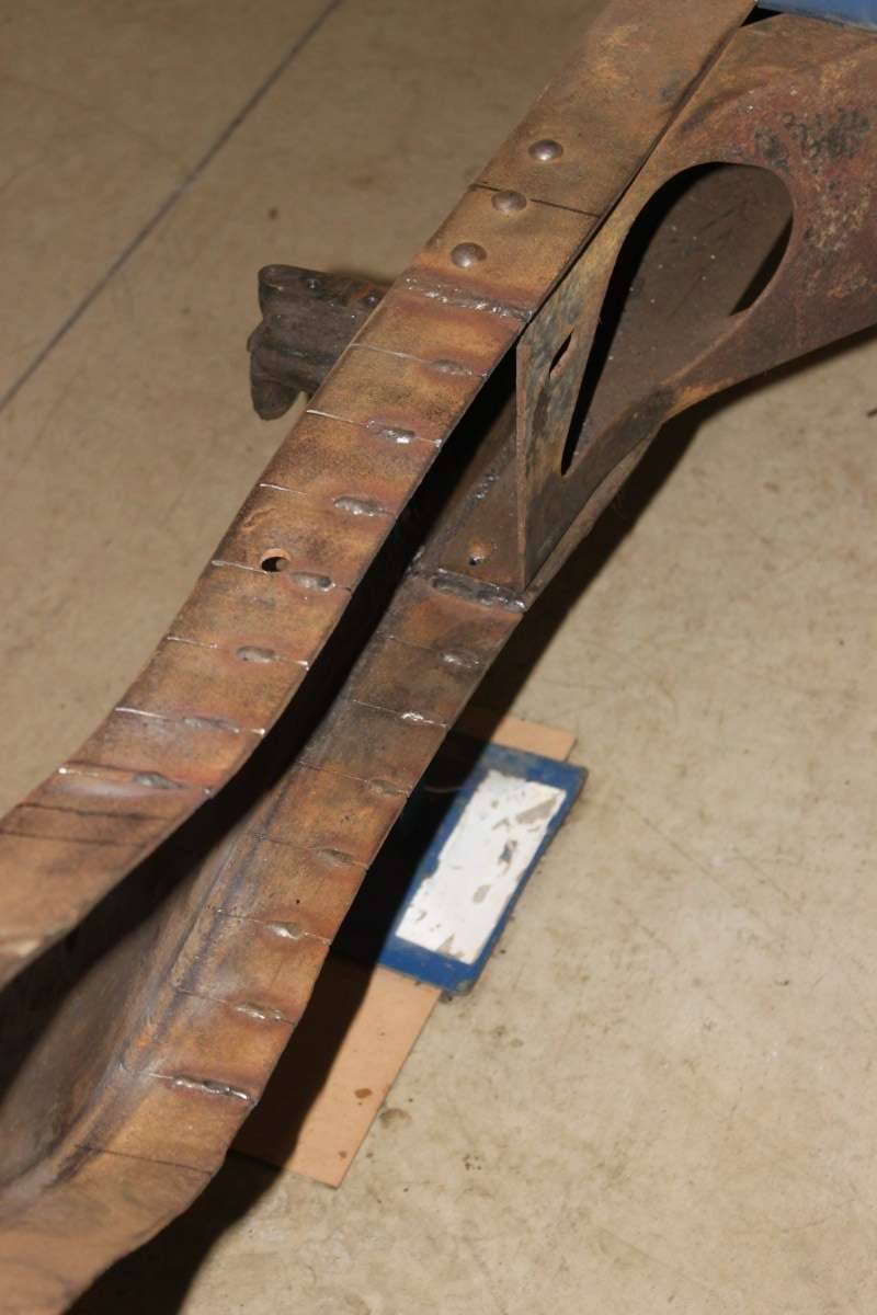 (89.27 KB)
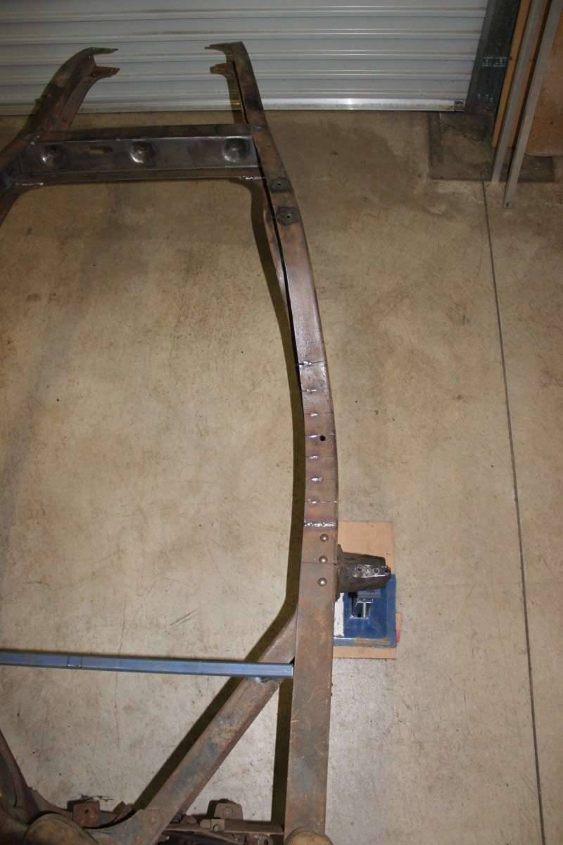 (92.71 KB)
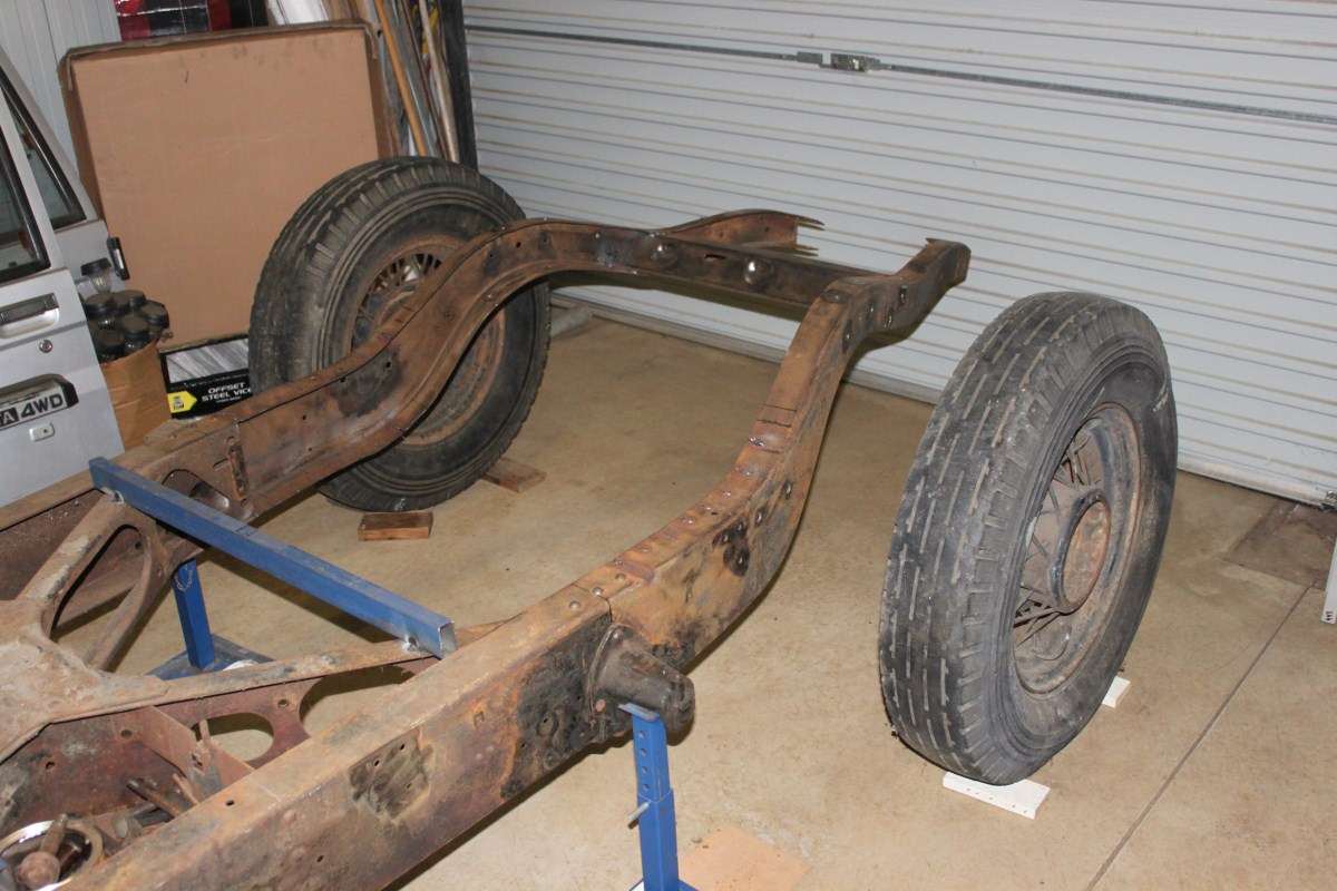 (97.40 KB)
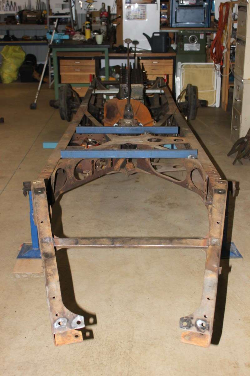 (85.11 KB)
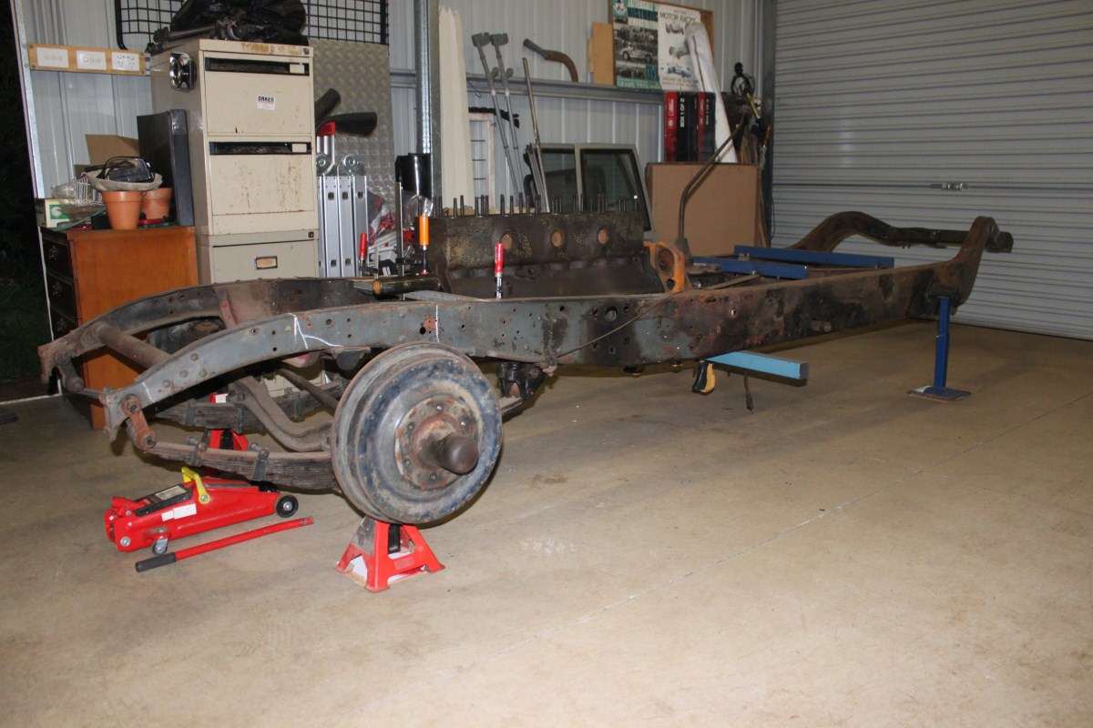 (101.79 KB)
This Post was from: https://packardinfo.com/xoops/html/modules/newbb/viewtopic.php?post_id=80916