Re: R11 O/D Fails to Electrically Engage
Posted by HH56 On 2014/10/4 13:23:21
I don't think changing the relay would be the first thing to do -- unless the contacts inside have somehow shorted to ground. The coil and command circuitry is fed from the ign switch via separate feed and may or may not be fused. It is possible the coil or a switch has failed but shouldn't be the cause of the fuse on relay blowing. You can see if the relay is activating by turning the key on and grounding the lead coming from kickdow switch. You should hear the relay coming in and bringing the solenoid in also. If you hear the relay but no solenoid then move to the solenoid part of the circuit.
The relay mounted fuse only protects the wire to solenoid and the solenoid coils so I'd check very carefully for a short in the wire going to solenoid that might be vibrating against the frame or have opened. If there was a short in the wire the fuse would blow and would explain one of the symptoms. If the wire shorted and burned open that might also explain the fuse and no operation.
If the wire is OK, also check the solenoid pull in coil disconnect contact inside the solenoid. That contact was a service item on the R9 and I think it is on R11s also. It can fail so a possibility is If the solenoid pull in contact stuck or welded and could not disconnect the pull in coil, the fuse would also blow but with fuse replacements, eventually the pull in coil could burn out and solenoid would no longer engage. With a fuse blowing, a somewhat less likely problem but also possible is the contact burned & now cannot close the circuit so the pull in coil can work.
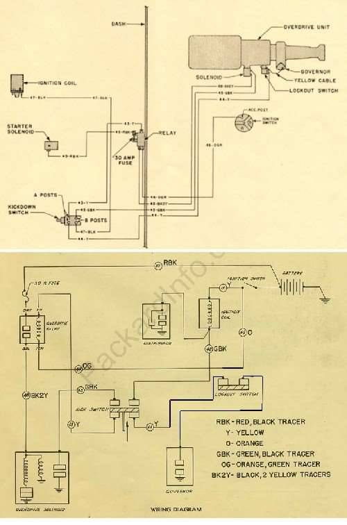
Here is a composite schematic--54 from wiring diagram and the complete R11. The original R11 schematic showed all the internal relay contacts but had a different lockout switch arrangement. That sw was in the power side under the dash. I revised this schematic slightly to show how the 51-4 changed when they moved the lockout switch to side of OD and inserted it in the ground side. Other than a couple of wire colors and the lockout sw position, everything else is identical from the earlier schematic.
Attach file:
 (72.57 KB)
The relay mounted fuse only protects the wire to solenoid and the solenoid coils so I'd check very carefully for a short in the wire going to solenoid that might be vibrating against the frame or have opened. If there was a short in the wire the fuse would blow and would explain one of the symptoms. If the wire shorted and burned open that might also explain the fuse and no operation.
If the wire is OK, also check the solenoid pull in coil disconnect contact inside the solenoid. That contact was a service item on the R9 and I think it is on R11s also. It can fail so a possibility is If the solenoid pull in contact stuck or welded and could not disconnect the pull in coil, the fuse would also blow but with fuse replacements, eventually the pull in coil could burn out and solenoid would no longer engage. With a fuse blowing, a somewhat less likely problem but also possible is the contact burned & now cannot close the circuit so the pull in coil can work.
Here is a composite schematic--54 from wiring diagram and the complete R11. The original R11 schematic showed all the internal relay contacts but had a different lockout switch arrangement. That sw was in the power side under the dash. I revised this schematic slightly to show how the 51-4 changed when they moved the lockout switch to side of OD and inserted it in the ground side. Other than a couple of wire colors and the lockout sw position, everything else is identical from the earlier schematic.
Attach file:
(72.57 KB)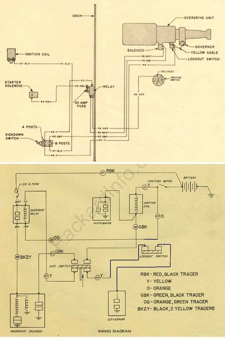
This Post was from: https://packardinfo.com/xoops/html/modules/newbb/viewtopic.php?post_id=150797