Re: 54 Convertible Turn Signal Issues
Posted by HH56 On 2022/3/31 12:41:43
Checking grounds and connections one by one is the next step. The original thermal type turn signal flashers rely on having the correct resistance in the overall circuit -- mostly determined by bulbs and corrosion free connections and grounds -- to provide the proper conditions for the flasher to work. When the switch is placed in a turn position that completes a path to ground and the resistance thru the bulbs and wiring allows the heater in the flasher to start and work a bimetal strip. Too much or too little resistance causes the flashers to have a fast action or none at all.
Because of the way the entire circuit is constructed with the bulbs in parallel and a shared filament in the dual filament bulbs using what may be a poor ground, a high resistance at one socket will have the circuit seek another way to a better ground either thru an unrelated filament at another bulb on the same circuit or in the case of grounded indicator lights, thru what should be an isolated bulb.
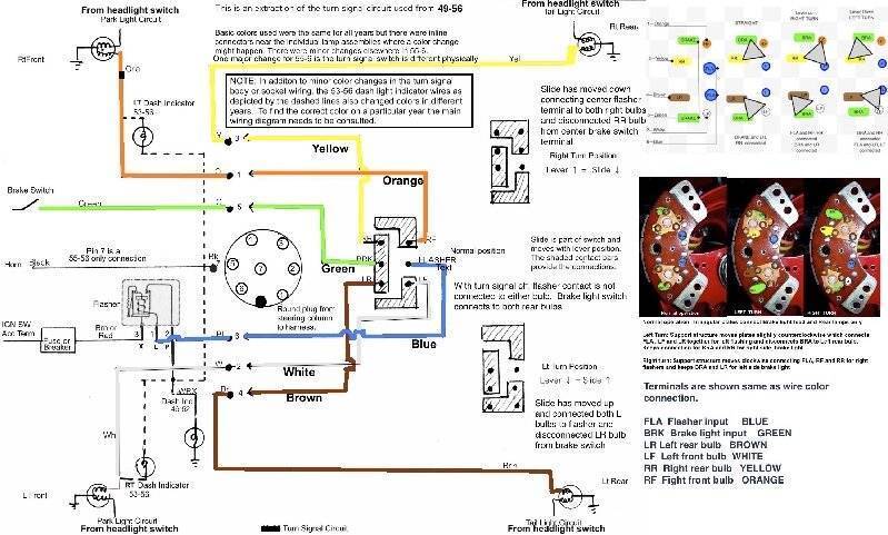
I don't know if you have the simplified turn signal drawing that has been posted before but if not, here is an extraction showing only the turn signal circuit and how the flasher output power and brake light switch output goes thru the switch to reach the various bulbs. Note that the turn signal switch contacts can get dirty and are supported on fiber insulation sheet which can warp and move a contact out of position. A poor connection in the switch can also cause intermittent or strange operating conditions.
Attach file:
 49-56 Turn Signal Extraction2.jpg (285.79 KB)
Because of the way the entire circuit is constructed with the bulbs in parallel and a shared filament in the dual filament bulbs using what may be a poor ground, a high resistance at one socket will have the circuit seek another way to a better ground either thru an unrelated filament at another bulb on the same circuit or in the case of grounded indicator lights, thru what should be an isolated bulb.
I don't know if you have the simplified turn signal drawing that has been posted before but if not, here is an extraction showing only the turn signal circuit and how the flasher output power and brake light switch output goes thru the switch to reach the various bulbs. Note that the turn signal switch contacts can get dirty and are supported on fiber insulation sheet which can warp and move a contact out of position. A poor connection in the switch can also cause intermittent or strange operating conditions.
Attach file:
49-56 Turn Signal Extraction2.jpg (285.79 KB)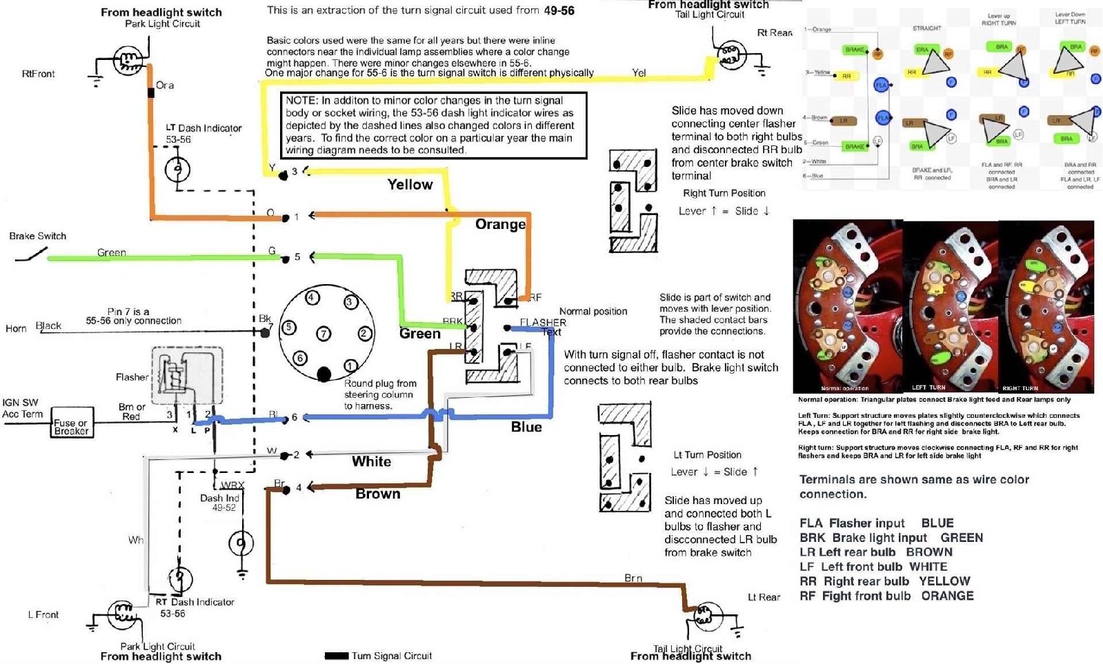
This Post was from: https://packardinfo.com/xoops/html/modules/newbb/viewtopic.php?post_id=242397