Re: Horn Relay
Posted by HH56 On 2023/7/21 15:41:46
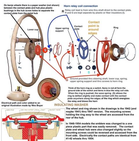
Here is a horn ring assy diagram that was used starting with 41 Clippers and was the same electrically for all thru 54. It is of a 47 wheel but shows the components and how the ground path starting with the steering shaft connects thru pieces to the contact area of the horn ring. When the ring is pushed, contact to ground is made and then sent back out to the wire running thru the steering shaft and finally ending at the relay S terminal.
While the electrical path is the same thru 54, the way the horn ring mounts to the wheel and how the horn button emblem is removed changed. 41-47 the horn ring is held by three small screws accessed thru holes drilled in the hub on the bottom side of the wheel. The emblem is in several pieces all held in the horn ring assy by a chrome ring and is not as easily removable as other years and type wheels. In 48-54 models the emblem is one piece and comes off with a push and slight twist CCW. 3 screws in the front side visible when the emblem is removed hold the ring to the wheel.
Attach file:
 horn ring electrical path.jpeg (50.21 KB)
While the electrical path is the same thru 54, the way the horn ring mounts to the wheel and how the horn button emblem is removed changed. 41-47 the horn ring is held by three small screws accessed thru holes drilled in the hub on the bottom side of the wheel. The emblem is in several pieces all held in the horn ring assy by a chrome ring and is not as easily removable as other years and type wheels. In 48-54 models the emblem is one piece and comes off with a push and slight twist CCW. 3 screws in the front side visible when the emblem is removed hold the ring to the wheel.
Attach file:
horn ring electrical path.jpeg (50.21 KB)This Post was from: https://packardinfo.com/xoops/html/modules/newbb/viewtopic.php?post_id=259548