Re: turnsignal switch
Posted by HH56 On 2019/3/7 9:54:01
If you compare the Packard switch to the built in Mitchell switch in the illustration they sure look like the same switch from above. Since the Mitchell piece says the switch was available to OEMs, maybe Packards system was copied from or built by Mitchell. It certainly could have been an add on type since the bulbs were independent and no wires in the Packard system thru the 22nd series were shared with anything else.
If your column has the studs to mount the switch and maybe a plug filling the hole for the lever, finding a switch should not be too difficult. The Clipper and maybe the Mitchell switch is a 3 wire and used thru the 22nd series. Doubt 23rd and later 6 wire switches will work because of the way lever mounts. The 3 wire switches are simple mechanically so worst case on a used switch after it is cleaned up is probably new wires would be needed. The steering wheel should have the holes for the cancelling pins and just needs a couple of roll pins added. The rest of the electrical is very simple so easy enough to put together following the Packard diagram. If your steering column can't handle a switch then probably best would be go to plan two and use the clamp on type housing.
IMO, the biggest issue on the Clipper will be finding the two bulb tail light housings needed for the extra bulbs in the rear and then running wires to each of the bulbs if there is nothing in the existing looms. No idea how much extra room there might be in your tail light housings but it might even be possible to add a hole for another socket for the bulb and use what you have.
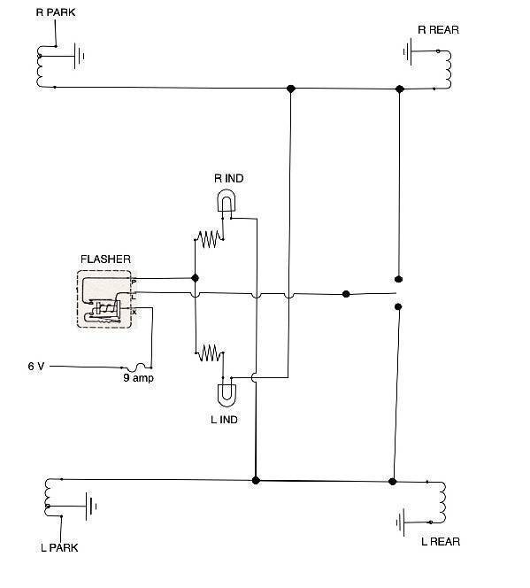
Here is a quick and dirty basic extraction showing the 46-7 Clipper senior turn signal circuit if you wanted to build it. No inline connectors etc are shown. What I do not remember is the value of the resistors used with the indicator bulbs so will need to find my notes from when I redid my 47 or failing that, try and measure them again -- unless someone else has the info. For 22nd series there was only a single indicator bulb connected directly to P on the flasher and ground. No resistor was used so would be a very simple circuit unless your speedo has the unused cutouts that really need two indicator bulbs. If no cutouts then you could add a discreet indicator lamp maybe in a bracket under the dash.
Attach file:
 (44.20 KB)
If your column has the studs to mount the switch and maybe a plug filling the hole for the lever, finding a switch should not be too difficult. The Clipper and maybe the Mitchell switch is a 3 wire and used thru the 22nd series. Doubt 23rd and later 6 wire switches will work because of the way lever mounts. The 3 wire switches are simple mechanically so worst case on a used switch after it is cleaned up is probably new wires would be needed. The steering wheel should have the holes for the cancelling pins and just needs a couple of roll pins added. The rest of the electrical is very simple so easy enough to put together following the Packard diagram. If your steering column can't handle a switch then probably best would be go to plan two and use the clamp on type housing.
IMO, the biggest issue on the Clipper will be finding the two bulb tail light housings needed for the extra bulbs in the rear and then running wires to each of the bulbs if there is nothing in the existing looms. No idea how much extra room there might be in your tail light housings but it might even be possible to add a hole for another socket for the bulb and use what you have.
Here is a quick and dirty basic extraction showing the 46-7 Clipper senior turn signal circuit if you wanted to build it. No inline connectors etc are shown. What I do not remember is the value of the resistors used with the indicator bulbs so will need to find my notes from when I redid my 47 or failing that, try and measure them again -- unless someone else has the info. For 22nd series there was only a single indicator bulb connected directly to P on the flasher and ground. No resistor was used so would be a very simple circuit unless your speedo has the unused cutouts that really need two indicator bulbs. If no cutouts then you could add a discreet indicator lamp maybe in a bracket under the dash.
Attach file:
(44.20 KB)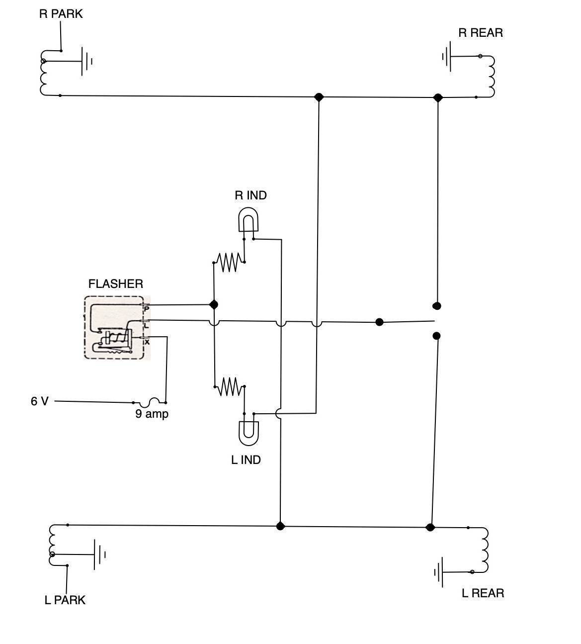
This Post was from: https://packardinfo.com/xoops/html/modules/newbb/viewtopic.php?post_id=209903