Re: 23rd Series - Flasher Plug Wiring
Posted by HH56 On 2024/2/22 12:12:54
On the flasher, X (3) is power in so that would get 26a BLY - blue with yellow tracer - from the fuse and ign switch. P (2) is panel so that would get 27 WRX - white with red cross tracer - to the indicator light and L (1) is signal lights so that gets 39 BL - blue - to the plug going to the turn signal switch. If you need to see the wire colors it might be necessary to carefully trim some of the fabric loom weave or tape wrap on the harness back to expose unfaded wire. Some flashers have the P-L-X stamped on the bottom next to terminals and if yours does that can help to orient the flasher.
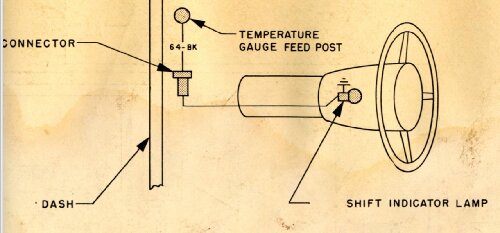
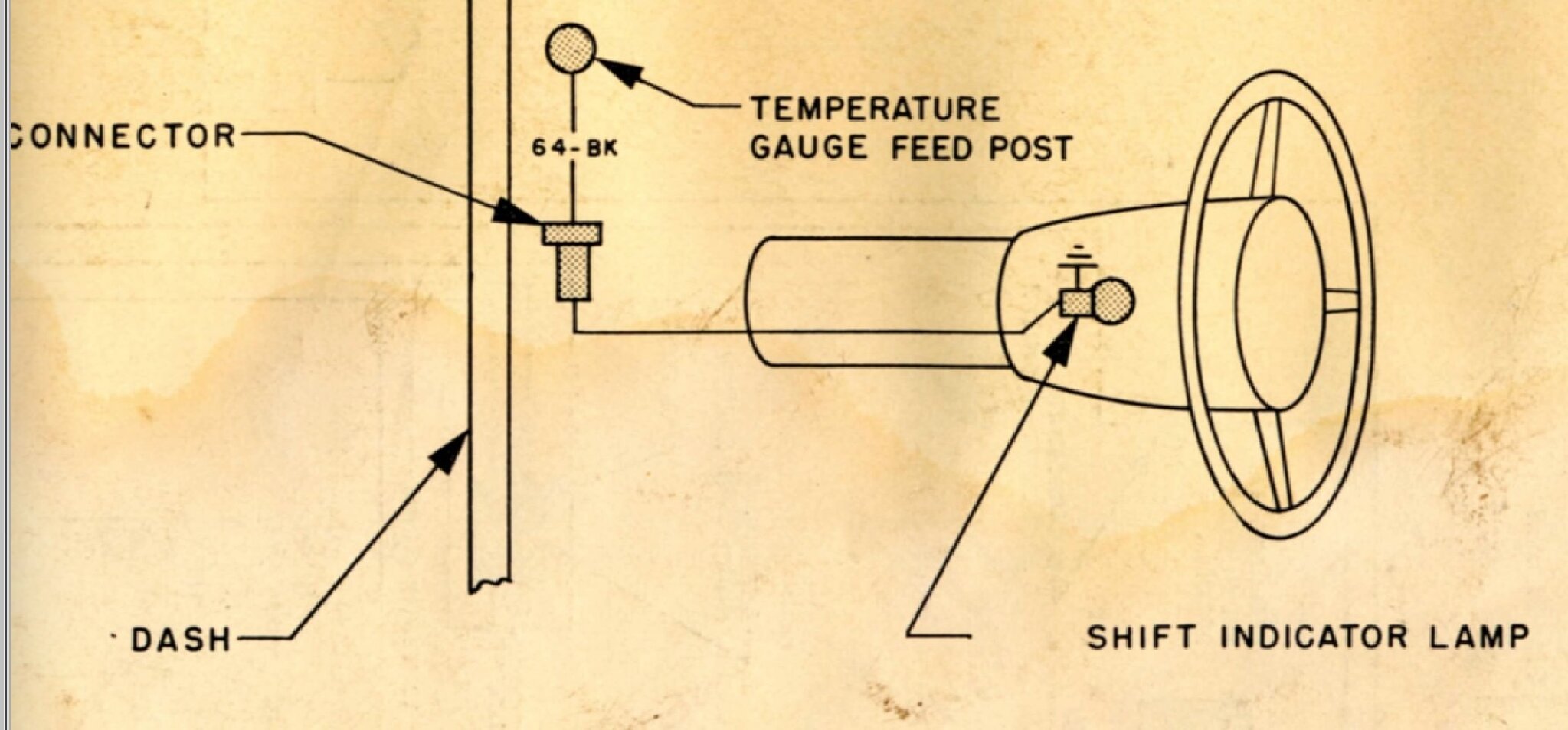
The Ultra indicator light is connected to the buss bar from ign switch GA terminal that feeds the gauges. In this case wire diagram says it is on the power in side of the temp gauge so indicator light is on any time the ign switch is in the run or right side on position. You may still have a wire pigtail and inline connector on the gauge terminal.
The Ultra indicator light is connected to the buss bar from ign switch GA terminal that feeds the gauges. In this case wire diagram says it is on the power in side of the temp gauge so indicator light is on any time the ign switch is in the run or right side on position. You may still have a wire pigtail and inline connector on the gauge terminal.
This Post was from: https://packardinfo.com/xoops/html/modules/newbb/viewtopic.php?post_id=268063