Re: T/L Manual Control Switch
Posted by BH On 2008/8/10 22:39:31
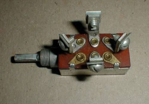
Now, there's a bit more to the manual control switch than meets the eye. It's more than a mere single-pole, double-throw (SPDT) switch for an electric antenna. (See Image 6492143, below.)
Although it has three pairs of terminals, do NOT confuse this three-way switch with a double-pole, double-throw (DPDT) switch. Rather, this switch uses a sliding contact to complete a circuit between one of the three pairs of opposing terminals, which involve three completely separate circuits.
The center set of terminals will be wired in series with the factory-installed under-dash cut-off switch ? a circuit which supplies power for the compensator control box. With the manual control switch in the center position and the under-dash compensator cut-off switch turned ON, the compensator control box functions automatically. When you move this control switch off of the center position, for manual operation, the compensator control box is effectively deactivated. As such, when you return the switch to the center position, the compensator will kick in UNLESS you have previously turned the compensator cut-off switch OFF. (This caveat is essential if you make Randy Berger's spring-loaded, center-return modification to this switch.)
Next, notice that only four of the six contacts have screw terminals. Two of the lugs on the switch run under crimps that hold the case to the terminal board and will be grounded. The opposing screw terminals will be wired in parallel with the compensator control box. Thus, moving the manual control switch off the center position will complete one of two circuits to ground ? doing exactly what the compensator control box would in its automatic mode. That ground path energizes a solenoid, which completes one of two field circuits and spins the compensator motor, but with the limit switches still wired in series to break the circuit to the solenoid, turn off the motor, and prevent over-travel of the leveling system. So, make sure your limit switches are in proper working order. In case of emergency, it also helps to have a battery ground cut-off switch installed.
Once you understand how this switch does the job, as Packard engineers intended, you may be able to make a substitution and wire up an equally safe and effective alternate solution yourself.
Attach file:
 (16.47 KB)
Although it has three pairs of terminals, do NOT confuse this three-way switch with a double-pole, double-throw (DPDT) switch. Rather, this switch uses a sliding contact to complete a circuit between one of the three pairs of opposing terminals, which involve three completely separate circuits.
The center set of terminals will be wired in series with the factory-installed under-dash cut-off switch ? a circuit which supplies power for the compensator control box. With the manual control switch in the center position and the under-dash compensator cut-off switch turned ON, the compensator control box functions automatically. When you move this control switch off of the center position, for manual operation, the compensator control box is effectively deactivated. As such, when you return the switch to the center position, the compensator will kick in UNLESS you have previously turned the compensator cut-off switch OFF. (This caveat is essential if you make Randy Berger's spring-loaded, center-return modification to this switch.)
Next, notice that only four of the six contacts have screw terminals. Two of the lugs on the switch run under crimps that hold the case to the terminal board and will be grounded. The opposing screw terminals will be wired in parallel with the compensator control box. Thus, moving the manual control switch off the center position will complete one of two circuits to ground ? doing exactly what the compensator control box would in its automatic mode. That ground path energizes a solenoid, which completes one of two field circuits and spins the compensator motor, but with the limit switches still wired in series to break the circuit to the solenoid, turn off the motor, and prevent over-travel of the leveling system. So, make sure your limit switches are in proper working order. In case of emergency, it also helps to have a battery ground cut-off switch installed.
Once you understand how this switch does the job, as Packard engineers intended, you may be able to make a substitution and wire up an equally safe and effective alternate solution yourself.
Attach file:
(16.47 KB)This Post was from: https://packardinfo.com/xoops/html/modules/newbb/viewtopic.php?post_id=10996