Re: 55 series vacuum hose routing.
Posted by HH56 On 2021/11/1 14:47:17
Packard never offered much in the way of documentation or photos for vacuum lines. You can find snippets in some of the factory photos but nothing all encompassing. The only factory documented vacuum hose diagram is after the two metal supply tubes on the engine. It has the the vacuum connections for the wiper motor and balance valve along with the washer.
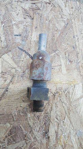
For a stock V8 wiper and washer there are two vacuum sources. Both have 1/4" steel lines to supply vacuum to the balance valve. The first or primary source has a 1/4" steel line connecting to a tee fitting at the rear of the carb. One opening on the tee is for the wiper and washer supply vacuum tube and the other opening has the power brake check valve threaded into it. The steel tubing goes toward the passenger side head and bends in a 90 back toward the firewall where it stops just past the end of the head and connects to a short rubber hose. It is clamped using one of the extra holes toward the rear of the head.
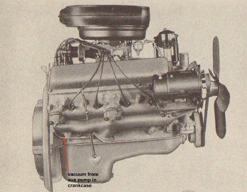
The secondary source for wipers is from an auxiliary pump in the crankcase. That port exits the block just above the oil pan and roughly behind the exhaust pipe flange. An elbow fitting threads into the block, a check valve threads into the elbow and another 1/4 steel line connects to the check valve. Valve is oriented so air flow is permitted to go toward the crankcase port but anything trying to pull from the crankcase is blocked. That tube goes to the end of the head and bends upward several inches where it connects to a short rubber hose going to the balance valve.
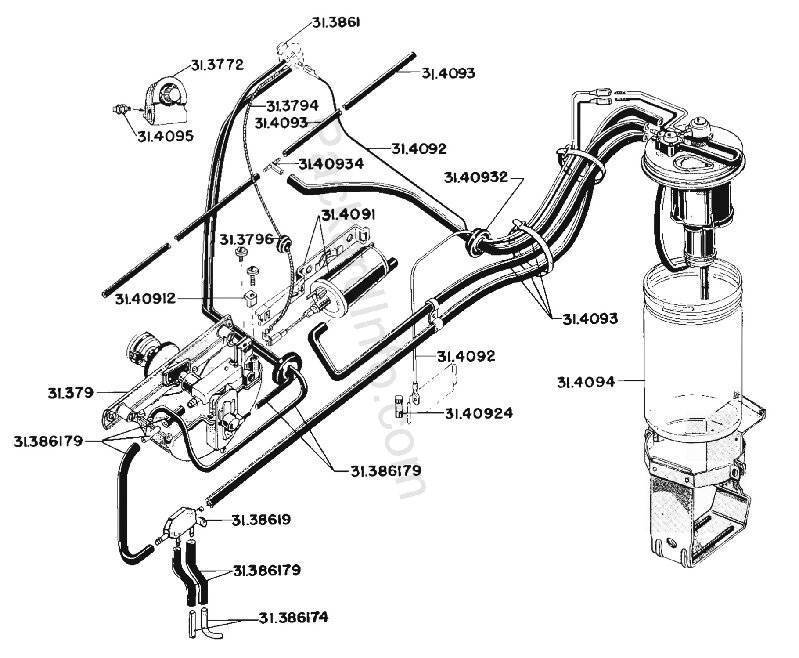
The power brake has a single hose just under 3/8" in diameter connecting to the check valve. It goes to the firewall where it gets a clamp and swings to the left just past the steering column where it goes thru another clamp and connects to a tee. The hose continues on from the tee to the vacuum reservoir tank under the left fender space. A short length of hose drops down from the tee and connects to the left side of the power brake booster. The only sort of documentation is in a 52 service counselor where there is an illustration showing the basic tubing connecting to the original style Treadlevac. That illustration is not really correct for a V8 because of the external air filter on the early Treadlevacs and the different source location on the inline 8.
Here are a few photos. The first is by Stewart showing the fitting and check valve at the rear of the carb. I don't have anything showing the top tube as I have a dual carb setup and that is different than the single carb. Second photo is from an engine manual showing the aux vacuum tube on the block. The third is the hose layout from the parts book.
Attach file:
 brake check valve and wiper supply tee.jpg (32.04 KB)
engine right side.jpg (253.88 KB)
washer tubing.jpg (216.31 KB)
For a stock V8 wiper and washer there are two vacuum sources. Both have 1/4" steel lines to supply vacuum to the balance valve. The first or primary source has a 1/4" steel line connecting to a tee fitting at the rear of the carb. One opening on the tee is for the wiper and washer supply vacuum tube and the other opening has the power brake check valve threaded into it. The steel tubing goes toward the passenger side head and bends in a 90 back toward the firewall where it stops just past the end of the head and connects to a short rubber hose. It is clamped using one of the extra holes toward the rear of the head.
The secondary source for wipers is from an auxiliary pump in the crankcase. That port exits the block just above the oil pan and roughly behind the exhaust pipe flange. An elbow fitting threads into the block, a check valve threads into the elbow and another 1/4 steel line connects to the check valve. Valve is oriented so air flow is permitted to go toward the crankcase port but anything trying to pull from the crankcase is blocked. That tube goes to the end of the head and bends upward several inches where it connects to a short rubber hose going to the balance valve.
The power brake has a single hose just under 3/8" in diameter connecting to the check valve. It goes to the firewall where it gets a clamp and swings to the left just past the steering column where it goes thru another clamp and connects to a tee. The hose continues on from the tee to the vacuum reservoir tank under the left fender space. A short length of hose drops down from the tee and connects to the left side of the power brake booster. The only sort of documentation is in a 52 service counselor where there is an illustration showing the basic tubing connecting to the original style Treadlevac. That illustration is not really correct for a V8 because of the external air filter on the early Treadlevacs and the different source location on the inline 8.
Here are a few photos. The first is by Stewart showing the fitting and check valve at the rear of the carb. I don't have anything showing the top tube as I have a dual carb setup and that is different than the single carb. Second photo is from an engine manual showing the aux vacuum tube on the block. The third is the hose layout from the parts book.
Attach file:
brake check valve and wiper supply tee.jpg (32.04 KB) engine right side.jpg (253.88 KB) washer tubing.jpg (216.31 KB)
This Post was from: https://packardinfo.com/xoops/html/modules/newbb/viewtopic.php?post_id=238295