Re: Super 8 Starter Wiring need some help!
Posted by HH56 On 2018/7/13 18:24:37
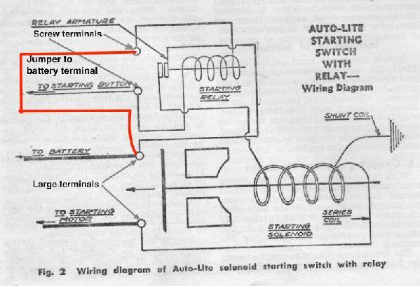
That appears to be the Autolite starter and solenoid which was used on the 356 engine thru 50.. The solenoid is actually operated by a small relay inside the square housing. The coil of that relay is what is brought out on the two small screw terminals.
There are two ways the start circuit was done prewar. The first is the starter needs a ground from the starter switch. Unless the car has had a modification, this method is shown on diagrams for the models with the starter button. On those that need a ground, usually the starter will energize by pushing the button even with the ign off. On models with the accelerator pedal start switch the starter needs a voltage and stater does not operate when ign is off. Some of the original ground needing models had a modification to make the circuit work like the accelerator switch type.
There is a safety circuit built in so in both cases the ground is provided either via the generator or in some models an extra set of contacts in the voltage regulator. This safety circuit prevents the starter from operating after the engine is running.
On models with a ground requirement, there is a very small almost hidden metal strip which jumpers between the battery post and one of the small screw terminals on the solenoid. If the solenoid has been painted the jumper may be painted over too. The other small solenoid terminal goes to the starter switch and after going thru the switch winds up at the voltage regulator. On regulators with an extra terminal labeled S or start there is a separate set of contacts associated with the cutout relay which connect to ground. Pushing the start button completes the ground to the solenoid.
The safety circuit works as follows: For the extra terminal on the regulator type, once the generator is putting out voltage and the cutout relay closes the extra contacts are opened so the starter button has no ground and cannot operate the solenoid. On regular voltage regulators with 3 terminals, the wire is connected to the ARM terminal which then goes thru the generator and finds a ground thru the brushes and armature windings. On those cars, when the generator starts putting out a voltage, that voltage is fed back to the regulator and one side of the starter switch. Since there is also voltage on the other side of the switch direct from the battery via the small jumper feeding the relay in the solenoid, the voltages are almost equal so there is not enough difference across the relay coil to bring in the relay and energize the solenoid.
On models with the accelerator switch, there is no small jumper at the solenoid so the voltage is taken from the ign switch. It goes thru the carb switch to one of the screw terminals on the solenoid The other start terminal is connected to the regulator ARM terminal and just as before, has ground coming from the generator.
Here is the Autolite solenoid diagram showing the jumper setup. The AEA diagrams available on the PAC site show the wiring. Depending on the quality of the print, the jumper is indicated by a very short and almost hidden line between the battery connection terminal and one of the small start terminals.
Attach file:
 (54.44 KB)
There are two ways the start circuit was done prewar. The first is the starter needs a ground from the starter switch. Unless the car has had a modification, this method is shown on diagrams for the models with the starter button. On those that need a ground, usually the starter will energize by pushing the button even with the ign off. On models with the accelerator pedal start switch the starter needs a voltage and stater does not operate when ign is off. Some of the original ground needing models had a modification to make the circuit work like the accelerator switch type.
There is a safety circuit built in so in both cases the ground is provided either via the generator or in some models an extra set of contacts in the voltage regulator. This safety circuit prevents the starter from operating after the engine is running.
On models with a ground requirement, there is a very small almost hidden metal strip which jumpers between the battery post and one of the small screw terminals on the solenoid. If the solenoid has been painted the jumper may be painted over too. The other small solenoid terminal goes to the starter switch and after going thru the switch winds up at the voltage regulator. On regulators with an extra terminal labeled S or start there is a separate set of contacts associated with the cutout relay which connect to ground. Pushing the start button completes the ground to the solenoid.
The safety circuit works as follows: For the extra terminal on the regulator type, once the generator is putting out voltage and the cutout relay closes the extra contacts are opened so the starter button has no ground and cannot operate the solenoid. On regular voltage regulators with 3 terminals, the wire is connected to the ARM terminal which then goes thru the generator and finds a ground thru the brushes and armature windings. On those cars, when the generator starts putting out a voltage, that voltage is fed back to the regulator and one side of the starter switch. Since there is also voltage on the other side of the switch direct from the battery via the small jumper feeding the relay in the solenoid, the voltages are almost equal so there is not enough difference across the relay coil to bring in the relay and energize the solenoid.
On models with the accelerator switch, there is no small jumper at the solenoid so the voltage is taken from the ign switch. It goes thru the carb switch to one of the screw terminals on the solenoid The other start terminal is connected to the regulator ARM terminal and just as before, has ground coming from the generator.
Here is the Autolite solenoid diagram showing the jumper setup. The AEA diagrams available on the PAC site show the wiring. Depending on the quality of the print, the jumper is indicated by a very short and almost hidden line between the battery connection terminal and one of the small start terminals.
Attach file:
(54.44 KB)
This Post was from: https://packardinfo.com/xoops/html/modules/newbb/viewtopic.php?post_id=204325