Re: Super 8 Starter Wiring need some help!
Posted by HH56 On 2018/7/13 22:24:10
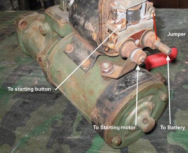
Here is a photo of a typical setup as it would be from the factory using the grounded starter switch. The labels are the same as was used in the drawing posted earlier. I don't have a factory voltage supply jumper on this starter but it is usually a thin copper strip. That could have been changed over the years to a wire or ??
IF the circuit has been modified so as to use the later circuit with voltage coming from the button instead of a ground the ground for the relay could be provided one of two ways. Keeping the safety circuit intact would be preferred but there were issues with the circuit in some cars -- particularly if the generator might have had some issues of its own. In that case the ground could be provided directly.
Factory bulletins had the mechanics remove the wire coming from the starter button at the regulator ARM terminal and ground it directly. It is also possible the factory jumper that was used to provide voltage in the grounded switch circuit was removed or repurposed and connected to some ground point on the starter or solenoid instead. Mechanics could have done it any number of ways so look or feel very carefully for any kind of connection between either of the small screw terminals to anywhere else on the solenoid or motor..
The solenoid has two windings. The shunt winding in the drawing is a very thin wire connecting to ground and is used only for holding the solenoid in once it has been energized. It cannot pull the solenoid in by itself. The one labeled series winding is very heavy wire that is for doing the heavy work but can only be for short time use. It goes thru the starter motor windings to find a ground much as the solenoid relay safety circuit goes thru the generator for its ground. The starter motor must be connected to the solenoid for it to work. Once the series winding has done the heavy job of pulling in the plunger it is effectively shorted out by the plunger connecting the motor terminal directly to the battery so quits doing any work leaving the shunt winding only to hold the plunger in.
The battery cable connects to the long terminal post which should be the one on the right in the photo. When the solenoid energizes a contact inside connects the battery terminal to the short post which has a buss bar direct to the motor. Assuming you are working on the 40 model in your signature, you can download the AEA diagram for you car from the PAC site it you do not have one. It very clearly shows the factory wiring from the solenoid thru the starter button to the regulator for the original circuit. If you car has been modified to more follow the 42 circuit which needs voltage instead of ground then it is anyone's guess exactly how it was done. As far as I know Packard never published a recommended method for that modification yet there are several cars I have seen which have been changed so the ign switch has to be on for the starter to work..
Attach file:
 (185.67 KB)
IF the circuit has been modified so as to use the later circuit with voltage coming from the button instead of a ground the ground for the relay could be provided one of two ways. Keeping the safety circuit intact would be preferred but there were issues with the circuit in some cars -- particularly if the generator might have had some issues of its own. In that case the ground could be provided directly.
Factory bulletins had the mechanics remove the wire coming from the starter button at the regulator ARM terminal and ground it directly. It is also possible the factory jumper that was used to provide voltage in the grounded switch circuit was removed or repurposed and connected to some ground point on the starter or solenoid instead. Mechanics could have done it any number of ways so look or feel very carefully for any kind of connection between either of the small screw terminals to anywhere else on the solenoid or motor..
The solenoid has two windings. The shunt winding in the drawing is a very thin wire connecting to ground and is used only for holding the solenoid in once it has been energized. It cannot pull the solenoid in by itself. The one labeled series winding is very heavy wire that is for doing the heavy work but can only be for short time use. It goes thru the starter motor windings to find a ground much as the solenoid relay safety circuit goes thru the generator for its ground. The starter motor must be connected to the solenoid for it to work. Once the series winding has done the heavy job of pulling in the plunger it is effectively shorted out by the plunger connecting the motor terminal directly to the battery so quits doing any work leaving the shunt winding only to hold the plunger in.
The battery cable connects to the long terminal post which should be the one on the right in the photo. When the solenoid energizes a contact inside connects the battery terminal to the short post which has a buss bar direct to the motor. Assuming you are working on the 40 model in your signature, you can download the AEA diagram for you car from the PAC site it you do not have one. It very clearly shows the factory wiring from the solenoid thru the starter button to the regulator for the original circuit. If you car has been modified to more follow the 42 circuit which needs voltage instead of ground then it is anyone's guess exactly how it was done. As far as I know Packard never published a recommended method for that modification yet there are several cars I have seen which have been changed so the ign switch has to be on for the starter to work..
Attach file:
(185.67 KB)
This Post was from: https://packardinfo.com/xoops/html/modules/newbb/viewtopic.php?post_id=204337