Hello and welcome to Packard Motor Car Information! If you're new here, please register for a free account.  
Login
Username:

Password:

Remember me


Lost Password?

Register now!
FAQ's
Main Menu
Recent Forum Topics
Who is Online
231 user(s) are online (152 user(s) are browsing Forums)

Members: 1
Guests: 230

Don B, more...
Helping out...
PackardInfo is a free resource for Packard Owners that is completely supported by user donations. If you can help out, that would be great!

Donate via PayPal
Video Content
Visit PackardInfo.com YouTube Playlist

Donate via PayPal

Forum Index


Board index » All Posts (carfreak6970)


Re: Vacation Car - 56 Patrician
#61
Home away from home
Home away from home

CarFreak
Just a minor update. I was able to get the suspension working!! the car is on the skates and was able to get the car to level out on its own using the compensator switch I modified to what Howard and Riki did. Works well. It is the version without the micro switches.

Ill finishing building one more for a spare, test it then go on to cleaning the interior out of parts (by putting them on the car) and get the carpet installed that I finally got last week! moving along.

Posted on: 2023/6/27 11:56
 Top 


Re: DIY Torsion level control switch conversion
#62
Home away from home
Home away from home

CarFreak
I can not thank you guys enough for doing this! saved me a lot of hassle!

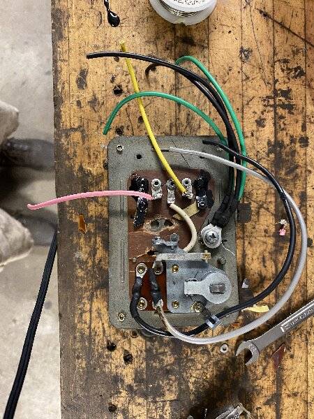
I did do something a little different. Howard is correct in that you NEED a powerful solder gun. Mine was nowhere near the 200W like he suggested, and the ones at work only went up to 140W. But I found another way:

so since your modifying the switch to the point original parts would no longer work, I cut one side of the contact that the relays would interact with and hammered out the other side. Doing so created a hole on top of that "L" contact. From there I wrapped the wire into that hole and around the top of the contact and a regular soldering iron was able to solder it properly.

Attach file:


jpg  IMG_1894.jpg (369.66 KB)
203788_6495a159e41cb.jpg 1440X1920 px

Posted on: 2023/6/23 8:42
 Top 


Re: Vacation Car - 56 Patrician
#63
Home away from home
Home away from home

CarFreak
Well, the entire front suspension is done! Disassembly wasnt difficult. I left the backing plates, and associated brake stuff on the knuckle and just removed the pivot bolts. The upper and lower control arms came out fairly easily. Upon disassembly I finally understood what my dad meant when he rebushed the car, he only did the control arm bushings.

pressing the bushings out of the upper arms were not bad at all. Pushing them in was a little tricky but it went together A okay.

I saw that a lot of people cut apart the lower control arms to get the bushings out, but with a punch and a decent size hammer they came right out. Again pressing them in was a little tricky, but got it done.

once the suspension was together, torqued at ride height I went on to installing the power steering hardware since my dad converted it to manual steering. Everything went together on the underside okay until I saw the power steering cylinder was hitting the exhaust. After doing some research I saw that the stove valve for the exhaust was installed on the wrong side, so once it was installed on the drivers side, it all went together okay. I took this time to change the cross(?) shaft seal on the bottom of the steering gear. I was a little annoyed that I had to partially disassemble the gear to change it, but I am glad I did. it was bone dry... No idea for how long, but I cleaned up the components, added the new seal and coated everything with a liberal amount of oil. I was letting everything sit before I fill the steering gear up.

Surprisingly I had a little extra time that I utilized to reworking 1 and almost two leverler control switches. Not to bad to do. Once I test fit the alternator Ill install the generator hook up the new switch and report back on how well it works on the car.

Posted on: 2023/6/23 8:32
 Top 


Re: Resurrecting my 56’ Patrician
#64
Home away from home
Home away from home

CarFreak
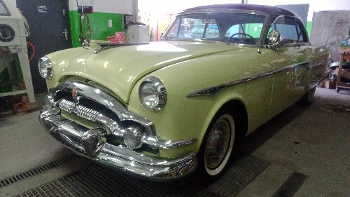
What did you use for tires? They look like they are brand new?

Posted on: 2023/6/19 10:34
 Top 


Re: Vacation Car - 56 Patrician
#65
Home away from home
Home away from home

CarFreak
Quote:

kevinpackard wrote:
Quote:

CarFreak wrote:
So I had to get some work done to my truck before the summer got into full swing, so now that is done I am back to focusing on the Patrician.

Got word that the carpet should hopefully ship in 2 weeks... hopefully. Been waiting a couple months for it.

last I heard on the seat covers is that they started it, ran out of material, created more material... I am due to follow up with them soon.

Didnt get a chance to modify one of my control switches to what Howard created. hopefully soon. I did start on re-bushing the rear suspension. I got mostly everything disassembled, going to try and get the big nut off of the front of the load arm tonight. Game plan is to have it disassembled and paint tomorrow and spend the holiday weekend getting the suspension back together.

Sounds like a good list to tackle. Your experience with the seat covers is what has me hesitating to have mine done at SMS. They are the only ones that have the right material, but I can order what I need and have someone local make them. It'll cost me a lot more, but with my car being driven I would rather pay more and have the car back on the road faster.

-Kevin


I dont blame you on that. I would have gone that route, but the door cards appeared in presentable shape and I wanted everything to match. Hopefully the seats dont make the door cards look too bad, but only time will tell.

thanks Riki! Ill keep that in mind

But as for an update, last week was busier than all hell, but I was able to get the entire rear suspension disassembled by having the car up on jack stands via the frame, put the axle on jack stands and just unbolted everything. I put a hydraulic jack under the load arms as the U bolts were undone and just lowered the load arms via the hydraulic jack once the U-bolts were undone. I did grab pictures of the U-bolts with a measuring tape just in case anyone would need to find new ones in the future.

but I got it all painted, rebushed, assembled, torqued and back on the ground! I hope to start on the front this weekend. Everything appears to be straight forward, I have the holding tool for the torsion bar.

is there any cutting that needs done to get the old bushings out? and do I really have to remove the backing plates from the steering knuckles/spindles? or can I just remove the knuckles/spindles by removing their pivots from the upper and lower control arms leaving the backing plates and brakes on? Besides taking pictures during disassembly so I know how it all goes back together, anything else I should be aware of?

thanks!

Posted on: 2023/6/6 16:58
 Top 


Re: Vacation Car - 56 Patrician
#66
Home away from home
Home away from home

CarFreak
So I had to get some work done to my truck before the summer got into full swing, so now that is done I am back to focusing on the Patrician.

Got word that the carpet should hopefully ship in 2 weeks... hopefully. Been waiting a couple months for it.

last I heard on the seat covers is that they started it, ran out of material, created more material... I am due to follow up with them soon.

Didnt get a chance to modify one of my control switches to what Howard created. hopefully soon. I did start on re-bushing the rear suspension. I got mostly everything disassembled, going to try and get the big nut off of the front of the load arm tonight. Game plan is to have it disassembled and paint tomorrow and spend the holiday weekend getting the suspension back together.

Posted on: 2023/5/26 16:20
 Top 


Re: DIY Torsion level control switch conversion
#67
Home away from home
Home away from home

CarFreak
Quote:

HH56 wrote:
If the switch fails, here is one way to eliminate the bimetal timing section and sometimes erratic contacts in the stock control switches by adding solid state time delay relays. No idea which vendors are selling the exchange switches so here is an option if an owner wants to do a conversion himself. Different relays may work better or not at all but I chose these because they were fairly inexpensive and readily available.

The relays I used are by INITEQ number INRXTD12X30B and are currently sold as a pair by Amazon. These are 12v 30 amp contact automotive type relays. Some Ebay vendors also sell a similar relay. Riki shows another brand in one of his posts. Space is extremely tight inside the control sw box. The INITEQ relays are 1 1/8” square x 1 15/16“ long. The flag terminal brings total length to 2 1/4”. Any larger relay may not fit and not sure if there would need to be any mods to the mounting bracket showing on the type relay Riki purchased. The easily found TD relays all seem to have a delay of 10 seconds which is longer than the factory specified 5-7 second delay but still a reasonable number.

First step was to unsolder 4 wires and unscrew the old relay bracket to remove the complete relay assy.

I could not find a way to avoid cutting the bimetal strips out of the box and still have the relays fit. A Dremel with cut-off wheel was used to cut the bimetal assy off the swivel bracket just as is done with the other solid state conversions. A couple of the old contacts were bent out of the way on the phenolic circuit board at the bottom to make room for the new support plate but nothing else needed cutting.

A hole was drilled in the pot metal for a new ground stud connection and two new wires were soldered to the existing pink and yellow terminals going to the outside. NOTE: Because the terminals have a large mass you will need a fairly high wattage soldering iron for this —at least 200 watts. New wires were also soldered back onto the terminals connected to the contacts operated by the lever and torsion bar. A regular wattage soldering iron will work for those. Because space is so tight I chose to use insulated flag style quick disconnects to connect the relays but those do need a special crimper. Another option would be to solder wires directly to the relays. If you do that make sure not to overheat the relay terminals and carefully insulate the terminals after the wires are on so they can not touch the cover.

A plate was also made to support the relays above the still existing contacts on the switch bottom. I chose to use a 1/16 thick phenolic material with dimensions of 1 7/8 x 2 1/8. Holes were drilled and countersunk in the plate to utilize the old relay bracket screw mounting location and threaded holes. The plate was placed on 1/2" standoffs using 3/4" screws. Note that the original relay bracket screws in the switch are an odd size -- 5-40 thread. That size is available but not typically found at local hardware stores. You could use easier to find 4-40 screws thru the original holes with a nut under the box to hold the screws or drill and tap the holes for 6-32.

IF you have a 55 switch, electrically they are the same with the main difference being the location of the terminals on the bottom. 55 switches had 3 exposed screw terminals and they are in different spots. Pink and Yellow wires would need to go to the different terminal locations.

Here are a few photos of a 56 switch as well as the new wiring diagram. NOTE: The wiring diagram is for the 56 Negative ground switch conversion. Wires 85 and 86 on each relay would need to be swapped for the 55 Positive ground. Both configurations test well on a bench but I will not be able to crawl under to test the conversion in a car.


Thank you so much for this!! this is amazing!!

when I finish maintenance up on my truck I will try this mod!!

Posted on: 2023/4/24 12:45
 Top 


Re: Vacation Car - 56 Patrician
#68
Home away from home
Home away from home

CarFreak
Quote:

HH56 wrote:
You might want to do a bit more research on what else will be needed in the circuit when using the 555 as the TL timer solution. As I recall, the 555 is somewhat sensitive and needs a fairly clean power supply or else operation becomes very erratic or chip doesn't work at all.

Auto electrical systems of that era are inherently "noisy" because of all the switches, coil and other ignition components, and even the generator brushes sparking. That activity is broadcast or directly connected to the same wiring used for voltage distribution so is picked up and carried all over. Evidence that by the various filter capacitors that need to be added at specific places to keep most of the electrical "noise" from being picked up and becoming static on the radio. You would probably need to add some conditioning directly to the power going into the chip.

Also, in that diagram the the load is shown as only being an LED which typically needs on average about 10ma to work. I don't know offhand how much current the 555 can directly power but depending on the relay used, you will probably need to have the timer chip trigger a transistor stage with the transistor being capable of carrying the current needed for the relay coil. The transistor stage will require a few components and the relay coil might also need conditioning so the back emf when the magnetic field collapses is not sent back to the transistor and damages it.

I went ahead and ordered a couple of stand alone timer relays that MIGHT work. Won't know for sure until they get here which should be tomorrow. If you can hold off a few days until I can test them it may be an easier solution. If they don't work then you can go to Riki's friend and see if he will make you a proper circuit assy or back to researching the 555 timer with only a bit of time wasted.

For anyone interested, here is an example of what is meant by electrical noise as shown on an oscilloscope. The heavy center dark line is ground, the heavy line at the top of the square pulses is 12v. On a clean power supply those lines would be extremely straight and much narrower. Notice the roughness in these lines along with the small spikes above the 12v line and the very large ones in the dashed box below the ground line. That is noise and in this case is caused only by the instrument voltage regulator contacts operating. Imagine what all the other switches could do when added to what is from only one component. Solid state circuitry can not work with that kind of activity on the power supply so various means of conditioning input voltage is required..


Yes I can wait! The fact that I know what needs done is a big weight lifted off my chest. The next step for this car is replacing suspension bushings that I hope to start in the next week or so.

Posted on: 2023/4/18 12:12
 Top 


Re: Vacation Car - 56 Patrician
#69
Home away from home
Home away from home

CarFreak
Quote:

R H wrote:
I.ll have to ask him to .


Its just. 2. Timing circuits..

On the web many diagrams.. Of timing circuits.

Its working in the relays.

With the timing relays. You can get on amazon. They also have adjustable ones but are expensive.

But its the same just figuring out the wiring.

And I was going to put them under the hood.

Just run wires from switch.


Okay, so I found this simple timing circuit:

http://www.learningaboutelectronics.com/Articles/555-timer-delay-before-turn-on-circuit.php

So the trigger would be from the rotating arm letting the switch know the car changed positions. Your input voltage would be from the green wire that is controlled by the dash switch. Your output would be going to the relay. Now how does the relay work (wiring it up) sending the ground signal to the limit switch?

Posted on: 2023/4/18 9:29
 Top 


Re: Vacation Car - 56 Patrician
#70
Home away from home
Home away from home

CarFreak
Quote:

HH56 wrote:
Quote:
I have not worked on my 1956 yet but I understand that the boxes were quite different for 1955. Is it possible that one of yours is that type?

The switch operation and except for the bottom terminal area inside the box, are identical. The main difference between 55 and 56 boxes is external. 55 had 3 exposed screw terminals which could corrode when wet so for 56 they changed to bullet type terminals and enclosed them in a weathertight box. They also added two extra double contact tie point terminals in that enclosure to accommodate the change of limit switch type. A service bulletin was issued noting that when 55 switches ran out the 56 switch was to be used and a short pigtail needed to be ordered and spliced to the 55 loom to connect to the different style terminals.

On your boxes, if cleaning the contacts did not work it almost sounds like you would be a candidate for a solid state switch conversion. Since the Pacific Northwest Region no longer lists them on their projects page I don't know if they still handle them or who else might. Believe the work was done on an exchange basis but maybe someone else knows a source.

If not, the conversions seem to be relatively simple. Photos posted seem to show the original relays and bimetal elements were removed and two time delay relays used in place of the original components. I don't have a photo of the solid state box to post but Riki might have posted some on one of his project blogs. Since the conversion is so simple I know he was doing some research on available relays Amazon carries to find some that might work. Don't know if he actually found one or did a conversion yet but maybe if he sees this post he can answer. Amazon does have a pair of 10 second delay cube types that might work but without actually doing a conversion myself I cannot say for sure they would work or fit inside the switch box.


Quote:

R H wrote:
I have not got to try the timing relays out.
But no reason they would not work.

The circuit board. A model train guy I know can make up a circuit board.

Then gerber file it to a pcb manufacturers..

Pretty cheap..

But also.

Was going to hit up hh56 about how to replace the solenoids with something solidstate.and heavy duty relays


This is all wonderful information thank you!! so if I want to get one of these working I got to start working on getting Box two fixed by finding out why the yellow terminal is always going to ground.

R H, that doesnt look to bad to replicate. I can try and do something like that if you dont have the time and dont mind sharing the gerber file, wiring diagram, and component information.

Posted on: 2023/4/17 10:02
 Top 


TopTop
« 1 ... 4 5 6 (7) 8 9 10 ... 23 »


Search
Recent Photos
Photo of the Day
Recent Registry
Website Comments or Questions?? Click Here Copyright 2006-2024, PackardInfo.com All Rights Reserved