|
Re: Synthetic 90 SAE
|
||||
|---|---|---|---|---|
|
Home away from home

|
I refilled my '56 differential with Amsoil 80w-90 synthetic gear lube after inspecting it. This was before the car was put back on the road, so I have no comparison. I have had no issues. I have been running synthetics in all my cars for decades.
Posted on: 7/18 16:02
|
|||
|
||||
|
Re: hph's 55 Clipper Project
|
||||
|---|---|---|---|---|
|
Home away from home
|
Joel has one NOS piston
Ebay
Posted on: 7/13 23:52
|
|||
|
||||
|
Re: hph's 55 Clipper Project
|
||||
|---|---|---|---|---|
|
Home away from home
|
What machine shop are you having do your work?
Posted on: 7/13 18:18
|
|||
|
||||
|
Re: Evapo-Rust
|
||||
|---|---|---|---|---|
|
Home away from home
|
I have used Evapo-Rust extensively with excellent results.
However, I have not used it on the coolant passages of an engine block or in a radiator. Have you flushed the cooling system? If so is it clean and does it flow well? The manual lists the radiator for the Six as having "Gravity flow new, 38 to 41 gallons per minute." Have you measured how hot it is when you say it "has a tendency to run hot in traffic and at idle."? The thermostat you put in was the correct 147 degree based on the part number. You haven't described it as hot enough to boil over.
Posted on: 7/10 13:04
|
|||
|
||||
|
Re: Fun with used cars
|
||||
|---|---|---|---|---|
|
Home away from home
|
Quote:
After parting out so many cars over the years its not hard for me to have all my favorite things. Where are Rodgers and Hammerstein and Julie Andrews when you need them?
Posted on: 7/5 12:17
|
|||
|
||||
|
Re: Ultramatic reactor end play measurement
|
||||
|---|---|---|---|---|
|
Home away from home
|
I have since acquired a PK-27 and have both in the tool collection.
Posted on: 6/27 4:36
|
|||
|
||||
|
Re: 352 onto an engine stand
|
||||
|---|---|---|---|---|
|
Home away from home
|
My 352 on a stand. I did use grade 8 hardware.
Attach file:  352OnStand.jpeg (1,205.05 KB) 352OnStand.jpeg (1,205.05 KB)
Posted on: 6/15 4:18
|
|||
|
||||
|
Re: hph's 55 Clipper Project
|
||||
|---|---|---|---|---|
|
Home away from home
|
I am happy with the work they did.
They did repair and testing and then I decided to have it recored. They put in a new style larger core. They do good work, in a reasonable time and stand behind it. The new core wasn’t inexpensive, but I wasn’t expecting it to be. So far it has been working and cooling well.
Posted on: 5/28 23:14
|
|||
|
||||
|
Re: hph's 55 Clipper Project
|
||||
|---|---|---|---|---|
|
Home away from home
|
I had my radiator tested and recorded at
Hunzeker Radiator Company 6800 Kelly Street Pittsburgh, PA 15208 412-661-2266
Posted on: 5/27 4:04
|
|||
|
||||
|
Re: V8 Engine Disassembly, Inspection
|
||||
|---|---|---|---|---|
|
Home away from home
|
The puller screw has to rest against the end of the crankshaft. The factory puller has a conical end which goes in the bolt hole and self centers. If you use washers, just make sure they aren't too big.
Attach file:  K-M-J-5992.jpg (207.46 KB) K-M-J-5992.jpg (207.46 KB)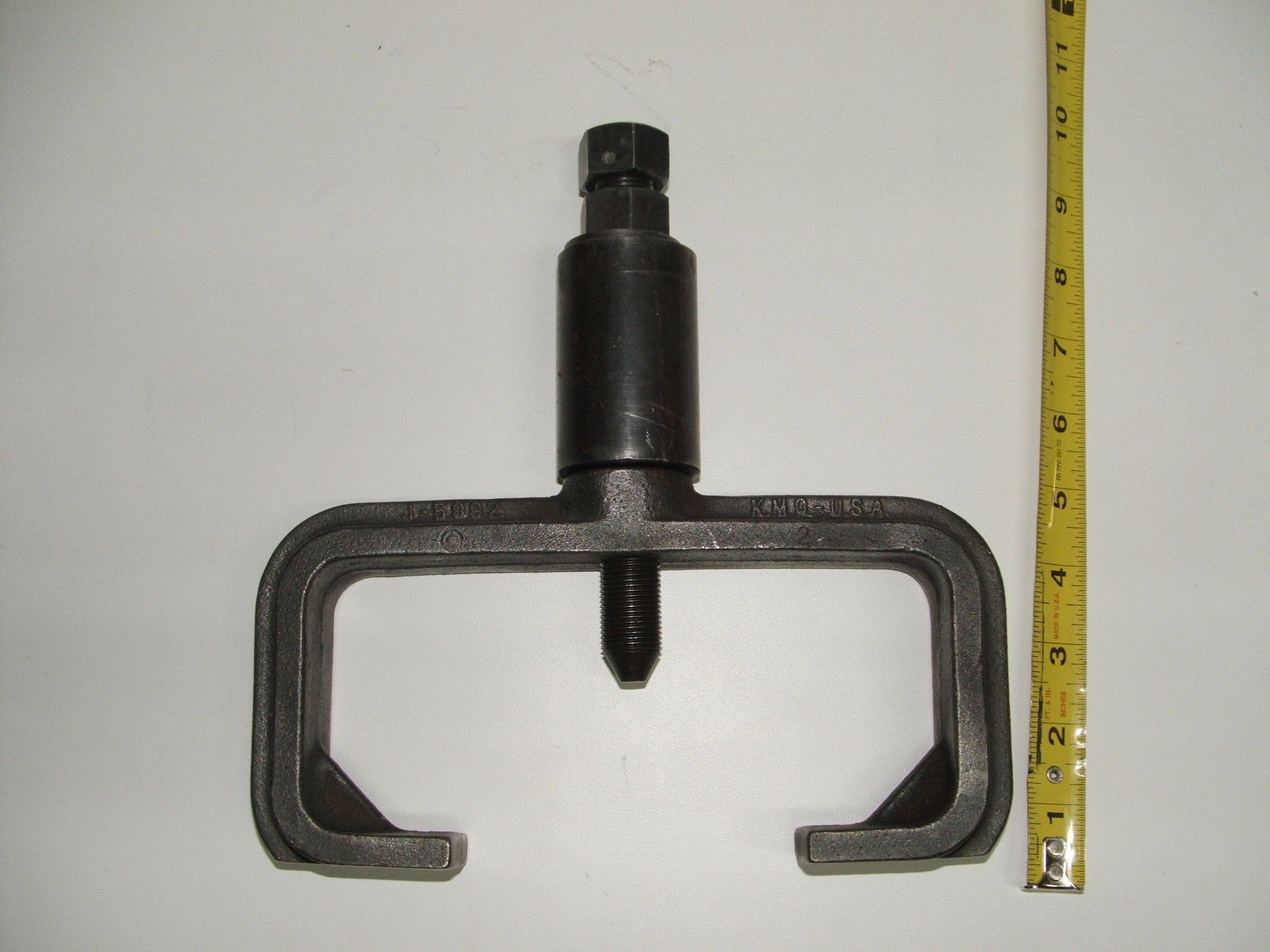
Posted on: 3/26 14:04
|
|||
|
||||


