|
Re: 1924 Sport 136
|
||||
|---|---|---|---|---|
|
Home away from home
|
Thanks for the tip Dave, I found the bolts in Bruce Blevins online catalog.
Karl
Posted on: Today 10:42
|
|||
|
||||
|
Re: 1924 Sport 136
|
||||
|---|---|---|---|---|
|
Home away from home
|
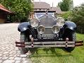
The snap rings and the retaining rings for the wheels are back. The chrome is striped and the nickel looks very good. Exept the bolts. These looks really bad after dechroming because they have had too much pressure on the edges. Does anyone know if the special bolts with this high nuts can be purchased as reproductions for these rims with the retaining rings ???
The dimensions are: 9/16 x 18 / length is 1.5" Karl Attach file:  k-P1040534.JPG (120.56 KB) k-P1040534.JPG (120.56 KB)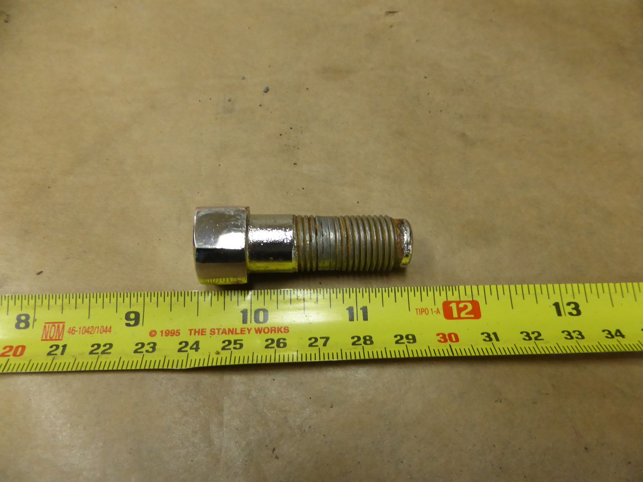
Posted on: Yesterday 10:45
|
|||
|
||||
|
Re: 1924 Sport 136
|
||||
|---|---|---|---|---|
|
Home away from home
|
A little update on the silencer... because the electroplating company didn't meet its deadline again... this time the excuse was... that the most important employee is on vacation for 5 weeks and the other one called in sick right today ... so I have to keep waiting and others prefer to work. I sandblasted the end covers and muffler brackets. .... by the way, .. the holders do not belong to the 136 Sport, these holders belong to the 236. The holders are therefore different, but can be easily adapted to the existing frame parts. I turned out the groove inside of the cover on the lathe. They now fit perfectly on the muffler housing tube. The gray cast iron lids have deep rust spots on the outside. For the sake of “visual correctness” I filled it with “Lab-Metal”. For the same reason I also rolled the 4 beads into the outer tube. This was not structurally necessary as the pipe is 2mm thick and therefore very stable. Back then, the beads were used to support the really thin sheet metal of the original muffle. More information about this when I compile the data for construction and renovation and post it here. Why do I pay so much attention to the purely visual work on a silencer....??? ... well, I want the visitors to the car shows and the judges who are always among the cars... to be satisfied and happy.
 Karl Attach file: k-P1040530.JPG (92.74 KB)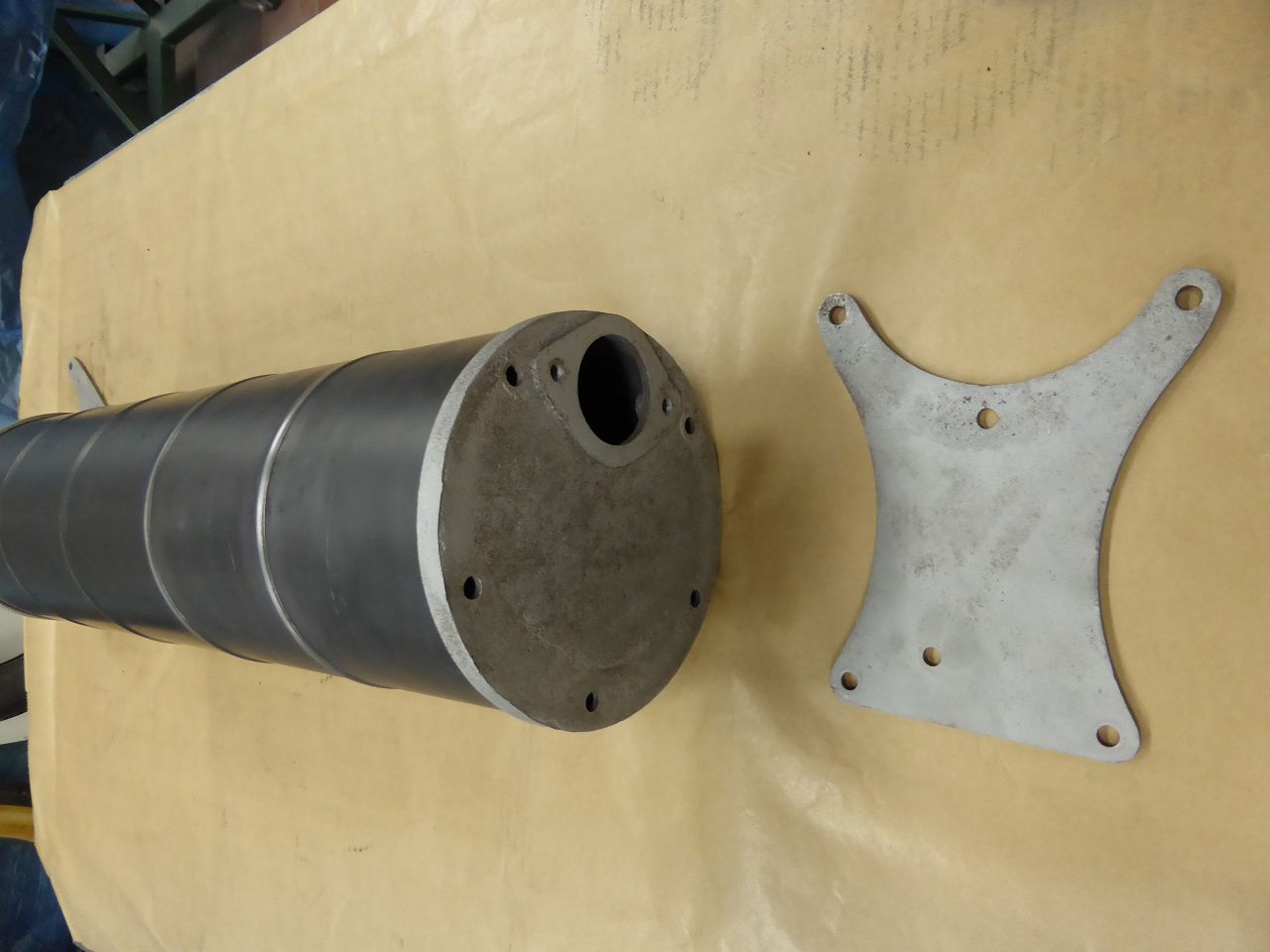 k-P1040532.JPG (104.50 KB) k-P1040532.JPG (104.50 KB)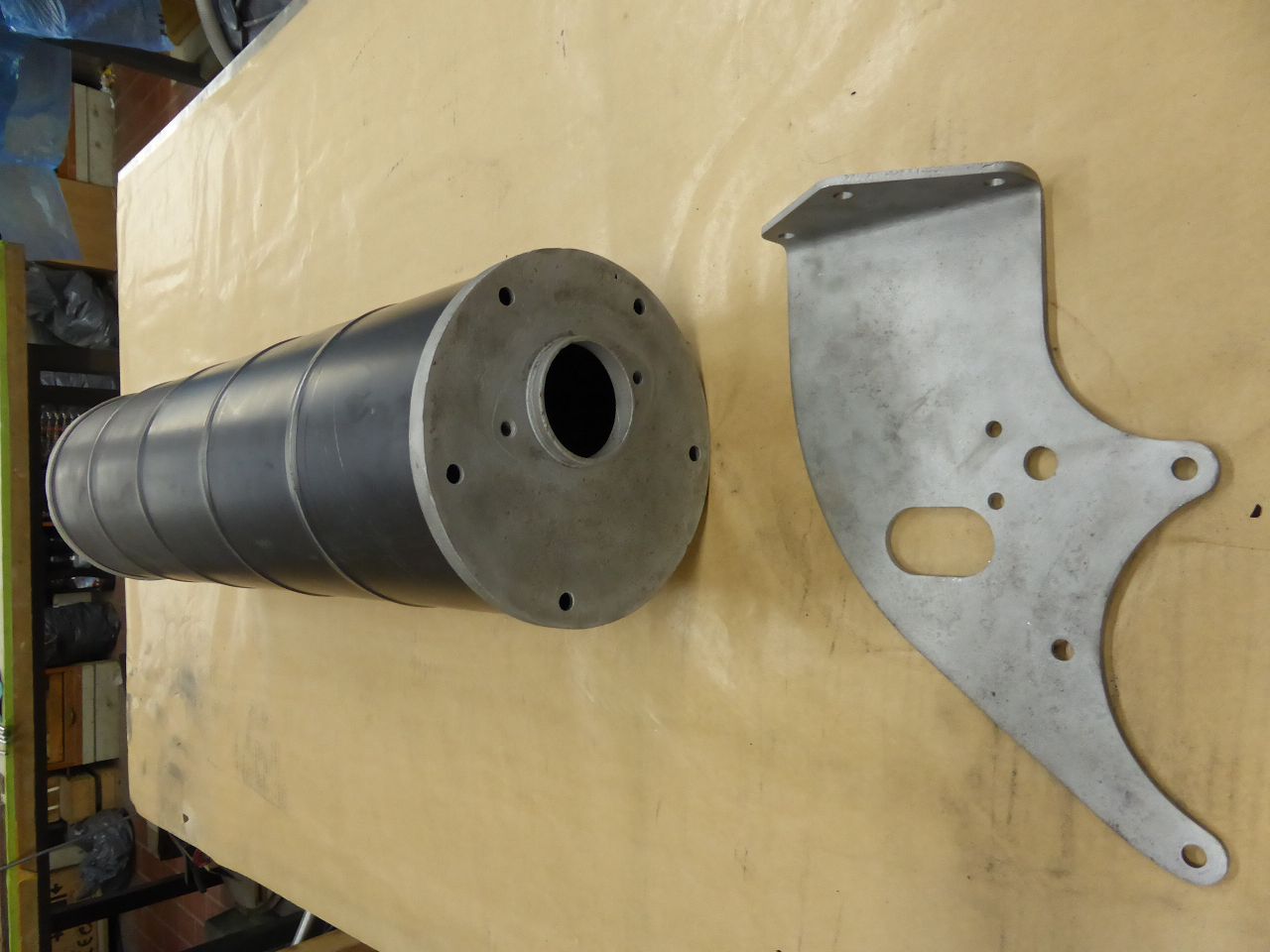 k-P1040533.JPG (122.61 KB) k-P1040533.JPG (122.61 KB)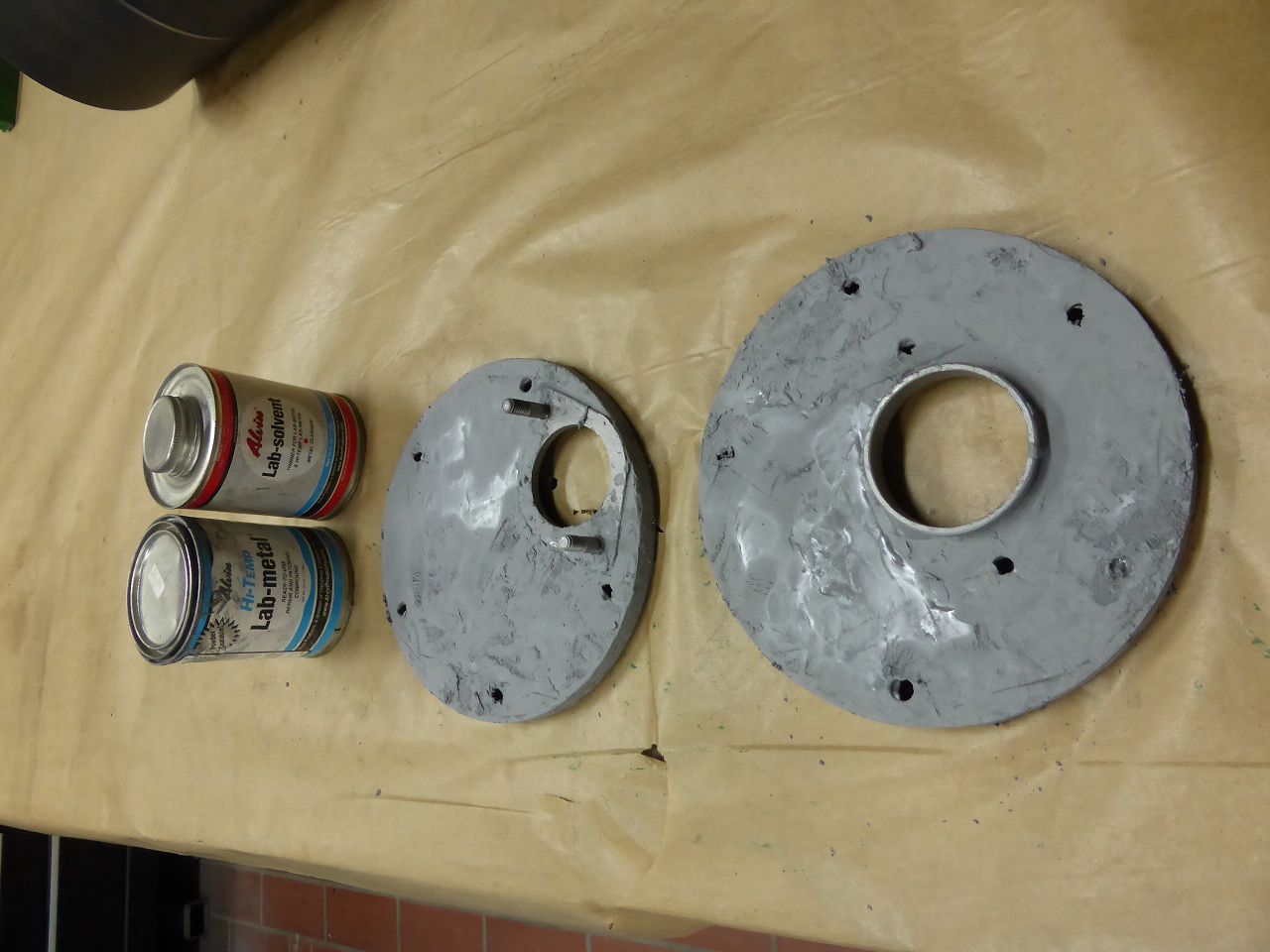
Posted on: 7/24 8:18
|
|||
|
||||
|
Re: 1924 Sport 136
|
||||
|---|---|---|---|---|
|
Home away from home
|
Don,
Thank you for your appreciative words about my work. It always gives me motivation for the remaining work on assembling the “Sport” and the work on the interior that still lies ahead of me. I hope to get the chrome-stript and newly nickel-plated snap rings, the rim retaining rings and the bolts back this week. Then I have to find a way to pull the snap rings onto the rims without damaging the paint. Karl
Posted on: 7/18 4:14
|
|||
|
||||
|
Re: 1924 Sport 136
|
||||
|---|---|---|---|---|
|
Home away from home
|
In the time between painting, I did the necessary work to mount the tires on the rims. For this I need the snap rings. But they are still chrome plated. And I need them nickel plated. So I prepared and assembled all the missing parts that still needed to be nickel plated and then had everything electroplated. Little by little there were still a few parts to work on. The clothes rail behind the front seat was still missing. The turn signal lights were not yet assembled and still needed work. In the Packard Accessories Catalog No. 52 on page 8 you could see these very suitable parking lights that can be used very well as turn lights. The problem was... where can I find two that fit? Surely there would have been some somewhere... at some point. But I don't have time to wait for it. So the only option was to recreate these lamps. The two cover rings of the lamps, in which the glass and the rear cover are housed, reminded me very much of the indicators on my Jaguar XK 140. It's good that I have such a vehicle in my workshop. It belongs to a friend of mine and is awaiting carburetor service. In any case, visually they are very similar to the Packard parking lights of the early 1920s.
All that was left was the housing. Based on the dimensions of the Jaguar lights, I looked for suitable brass tubes and found them from model makers who build steam machine models or steam-powered model trains. Not only did I find a pipe that was roughly the dimensions I was looking for, but it was also the exact size I was looking for. This also includes the lids that the model makers use to close the kettle. It was ideal for covering the parking light. The pictures explain the rest. So I ordered two Jaguar indicators, which ended up fitting perfectly into the replica housings. The biggest problem was the soldering work with silver solder. Joining thin brass parts with silver solder takes some practice and I haven't had that for a long time. Ultimately everything led to a good result. The rail robe was an accessory that I really wanted to have in my sport. But here too, building it yourself was the easiest way to get this component. I found the brackets online and modified them for my rail robe and joined them together with silver solder. The pipes are made of stainless steel. I shaped them with the acetylene flame and welded them together with stainless steel wire. I am very satisfied with the result. Karl Attach file: k-IMG_20240712_0001.jpg (282.78 KB)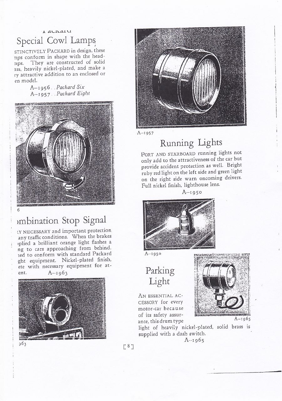 k-P1030083.JPG (105.02 KB) k-P1030083.JPG (105.02 KB)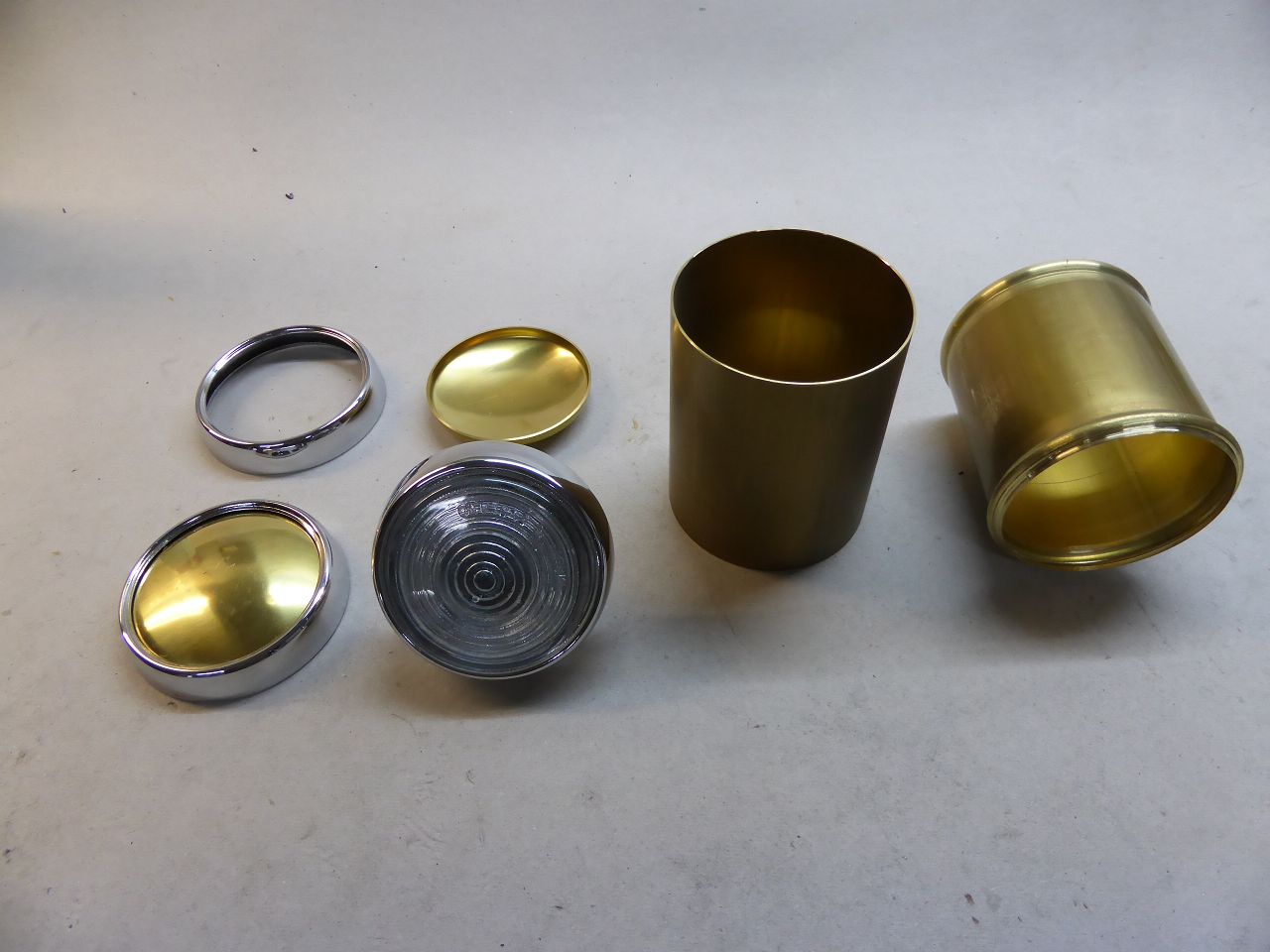 k-P1030084.JPG (140.80 KB) k-P1030084.JPG (140.80 KB)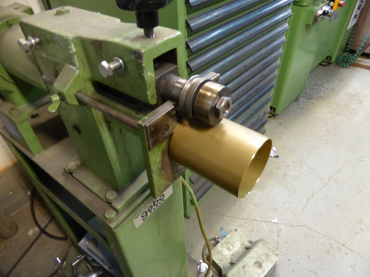 k-P1030085.JPG (99.94 KB) k-P1030085.JPG (99.94 KB)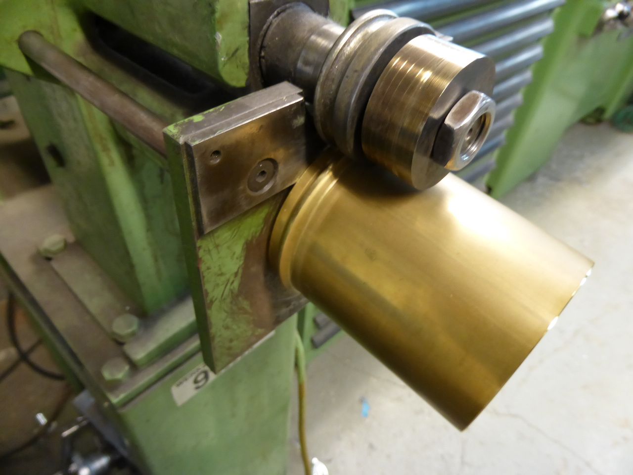 k-P1040504.JPG (121.62 KB) k-P1040504.JPG (121.62 KB)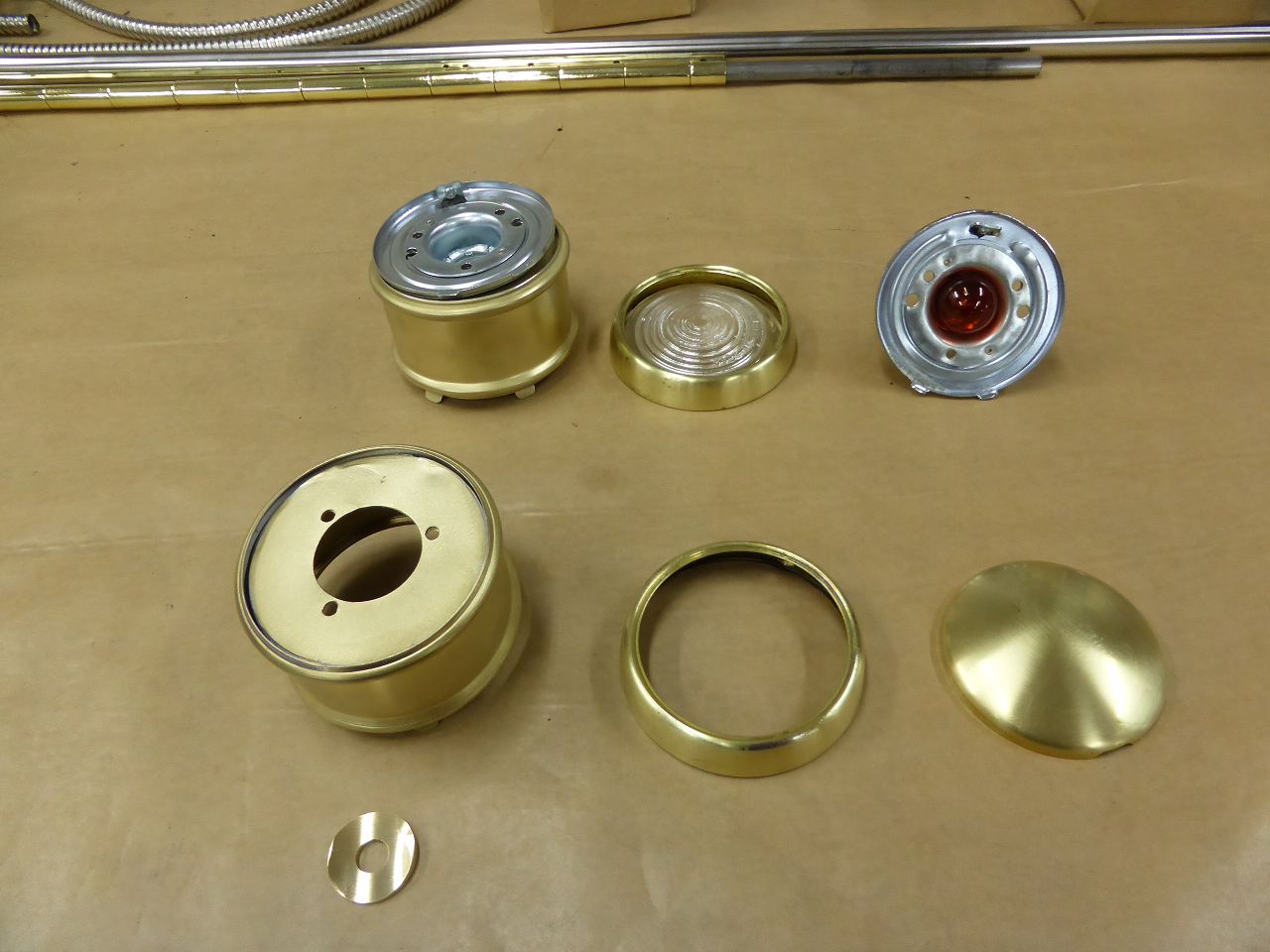 k-P1040505.JPG (100.63 KB) k-P1040505.JPG (100.63 KB)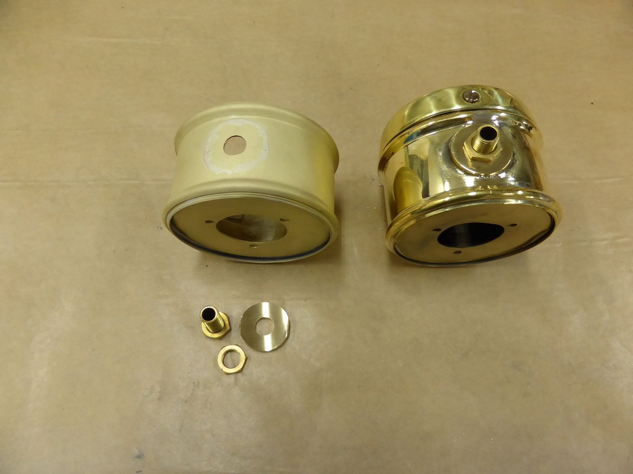 k-P1040506.JPG (97.10 KB) k-P1040506.JPG (97.10 KB)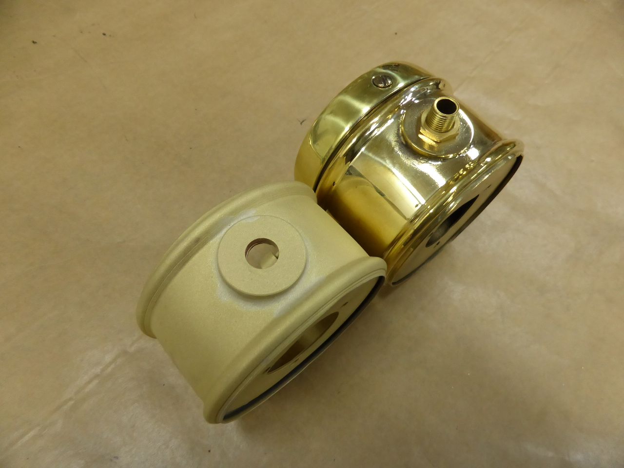 k-P1040521.JPG (168.22 KB) k-P1040521.JPG (168.22 KB)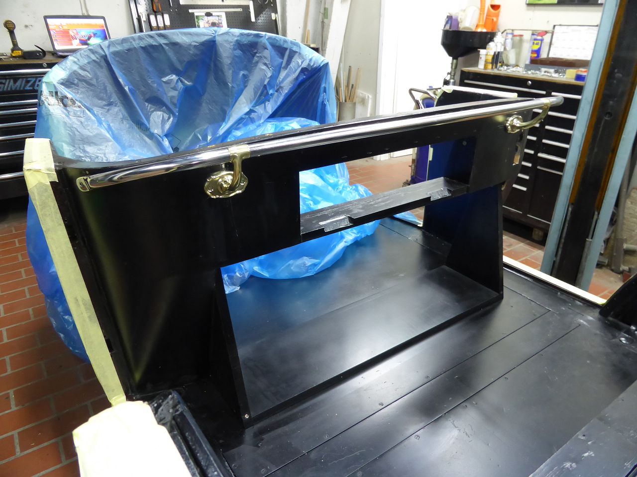 k-P1040522.JPG (180.63 KB) k-P1040522.JPG (180.63 KB)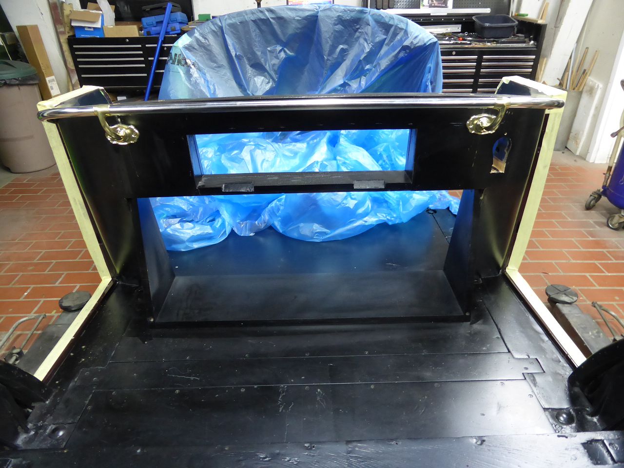 k-P1040527.JPG (105.12 KB) k-P1040527.JPG (105.12 KB)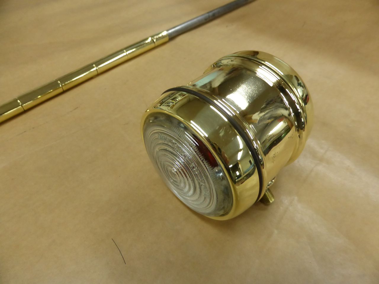 k-P1040528.JPG (108.12 KB) k-P1040528.JPG (108.12 KB)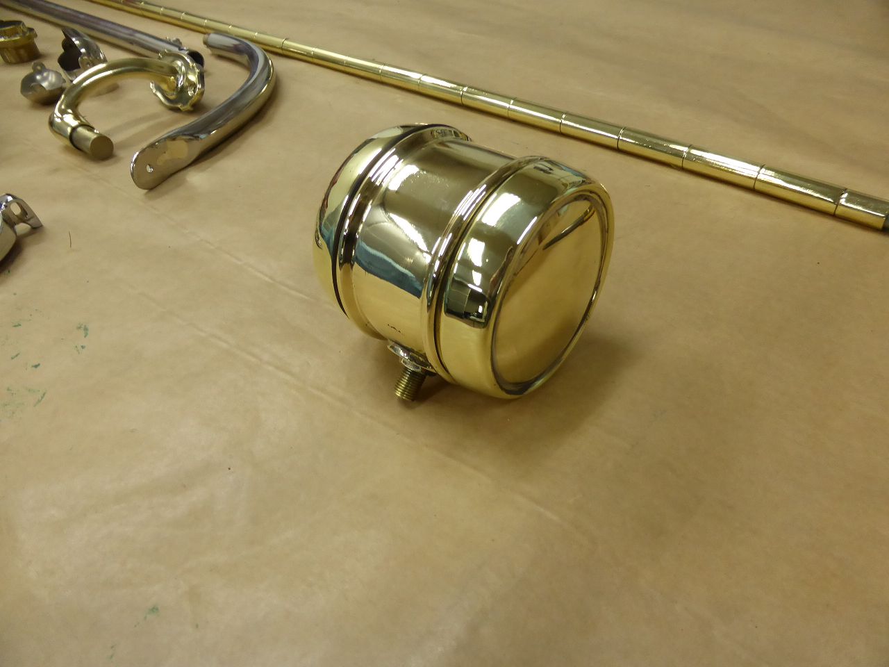 k-P1040525.JPG (108.97 KB) k-P1040525.JPG (108.97 KB)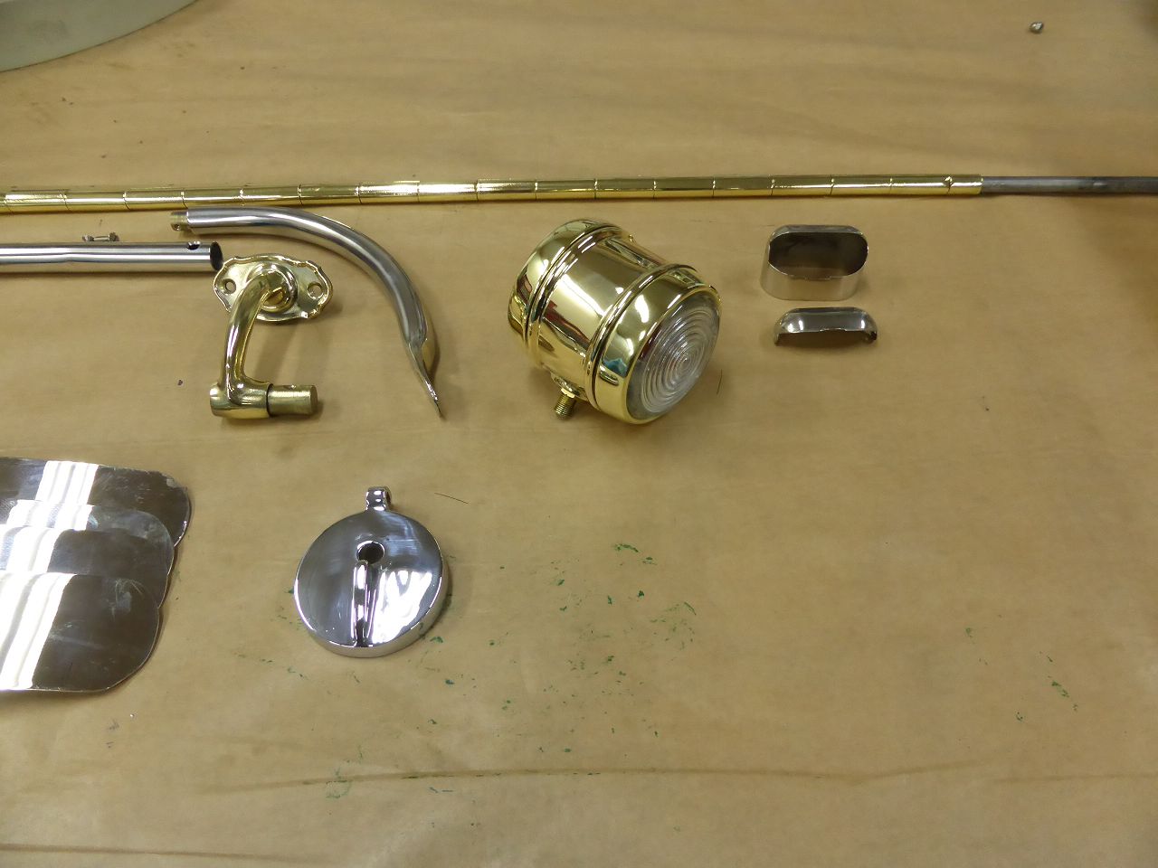 k-P1040526.JPG (132.56 KB) k-P1040526.JPG (132.56 KB)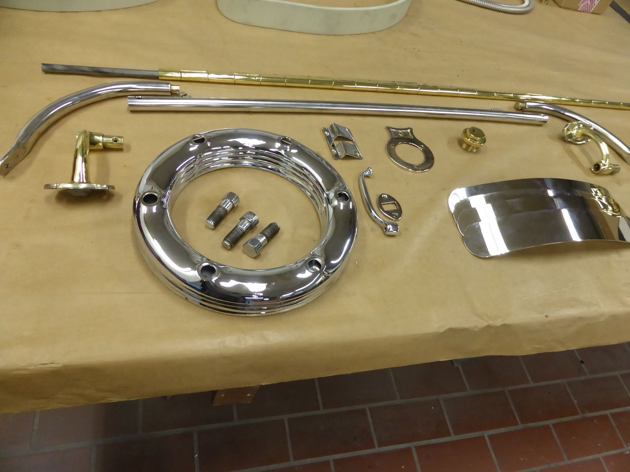 k-P1040503.JPG (139.38 KB) k-P1040503.JPG (139.38 KB)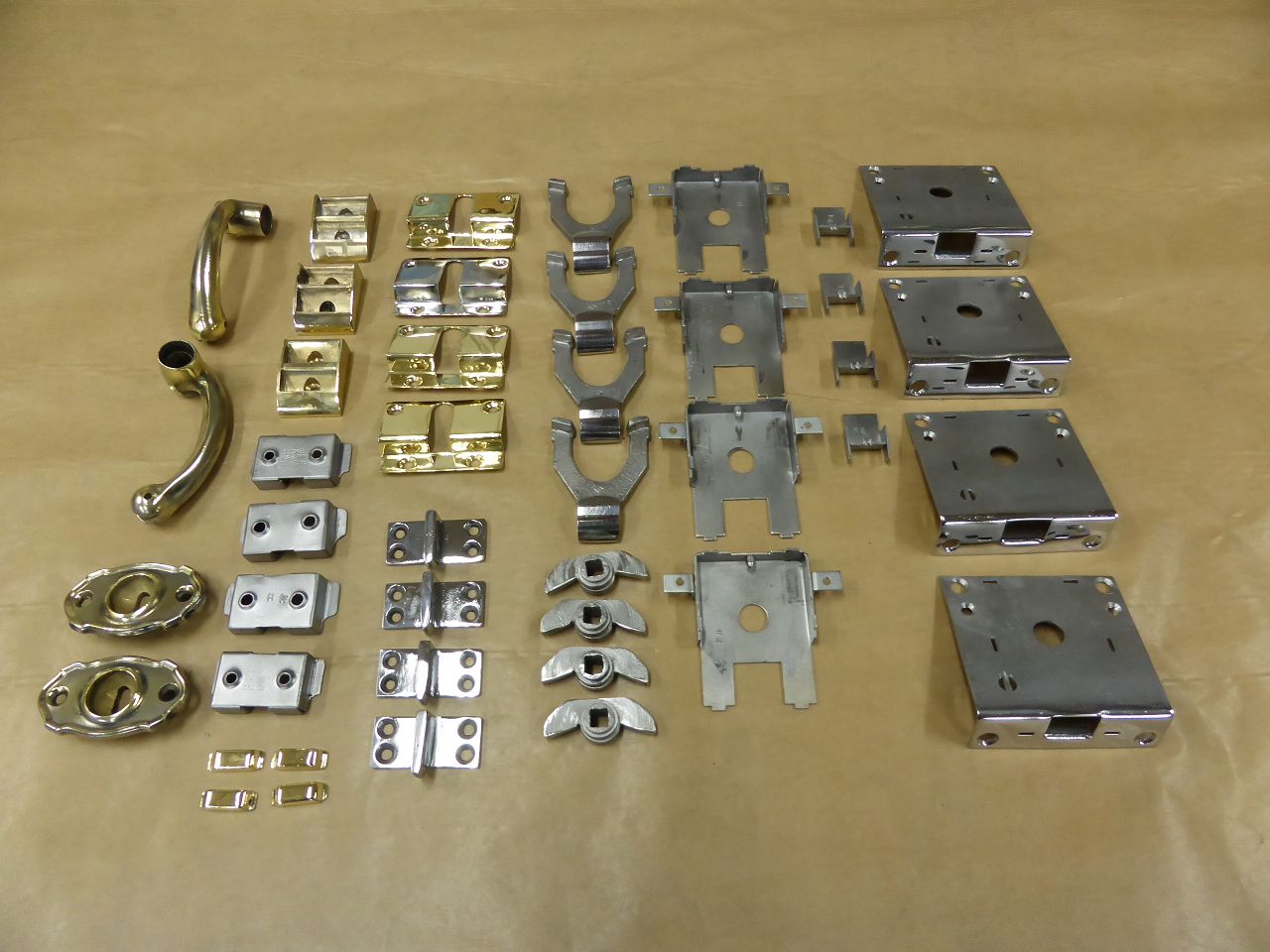
Posted on: 7/12 15:48
|
|||
|
||||
|
Re: 1924 Sport 136
|
||||
|---|---|---|---|---|
|
Home away from home
|
The last picture of the rims showed the dark filler before the final dark red paint. The filler was then sanded with an 800 grit foam pad and of course…. everything sanded by hand. The next picture (…0511) shows the rim painted in the vehicle color. For me... the top coat is as it should be. The next picture (...512) shows the next step... sanding the top coat like the filler with an 800 grit foam pad. For the final sanding I use a special abrasive fleece called "Super Assilex" from the company "Kovax". In the picture I show the 600 grit fleece...but I also used 800 for the finishing touches. Together with the foam pad... same company... you can achieve a very good result for the surface and the final clear coat. The fleece is also very soft and allows the edges to be sanded very carefully without sanding through. But be careful anyway... the fleece has a very sharp grain and one edge is quickly worn out. After thoroughly cleaning with silicone remover, I taped off the pinstriping area. To do this, I mounted the rims on my balancing machine and determined the position of the rings with a movable 0.5 mm black permanent marker on a tripod. ...Why I didn`t get a pinstripe guy and him apply the rings with a drag brush?? …. Well, there aren't too many people over here in Germany who have really mastered this art. And when you find one, he's reluctant to come over and work on five rims. Furthermore, the cost required relative to the work is… outrageous. The picture….0509 shows how I solved the problem. I applied the color that I chose myself using my Sata Minijet. Instead of 10%, mix with 30% thinner and paint in 2 layers. I then smoothed the edges of the line adhesive tape that were created despite the thinned paint using the 800 “KOVAX” fleece on the foam pad with very light finger pressure. So prepared, I took the rims to the paint shop and had the clear coat applied. The result is shown in the last image (…. 0516) on this topic. I only have 2 small holes on 5 rims and you can feel no steps at the strips. I am very happy with the result, especially considering the initial condition of the rims.
By the way...David,...I was thinking about using the color of the pinstripes for the bumper brakes and possibly the grease cups too. Do you remember... we talked about this in the "Pre-War Forum". Were the Grease Cups actually always and fundamentally painted in that familiar bright red??? The next work will be interesting. The aim is to get the snap rings over the rims without damaging the edges. I'll try it and report back here. Karl Attach file: k-P1040511.JPG (159.62 KB)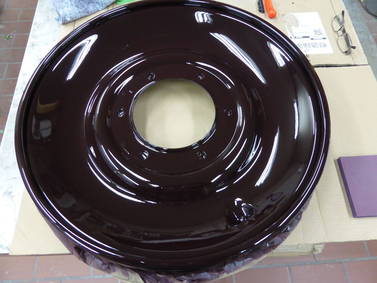 k-P1040512.JPG (124.78 KB) k-P1040512.JPG (124.78 KB)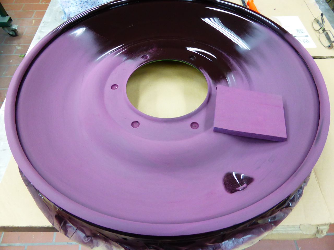 k-P1040513.JPG (150.01 KB) k-P1040513.JPG (150.01 KB)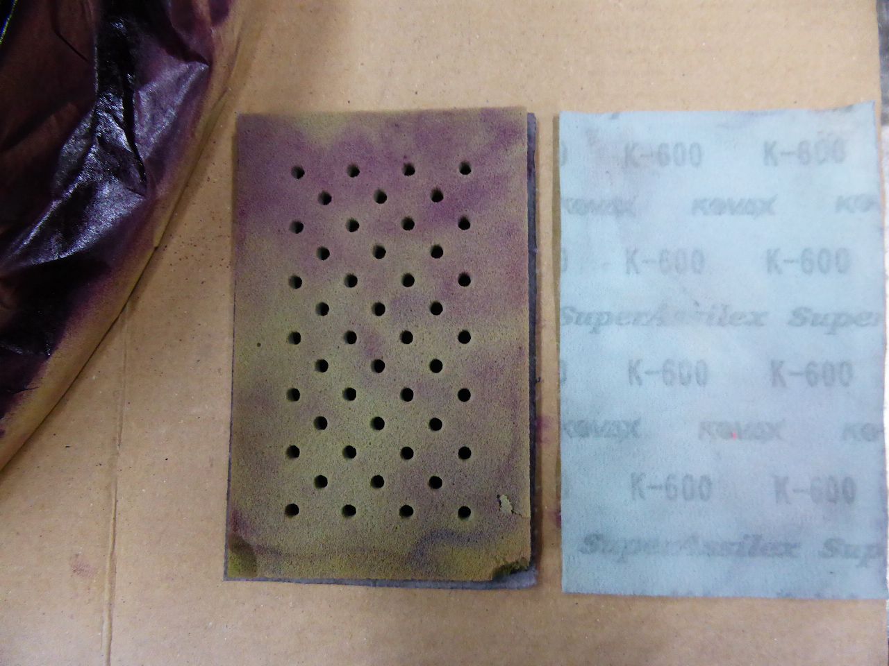 k-P1040514.JPG (107.21 KB) k-P1040514.JPG (107.21 KB)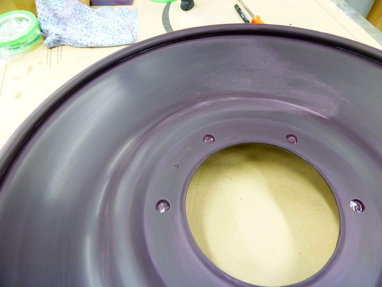 k-P1040509.JPG (162.50 KB) k-P1040509.JPG (162.50 KB)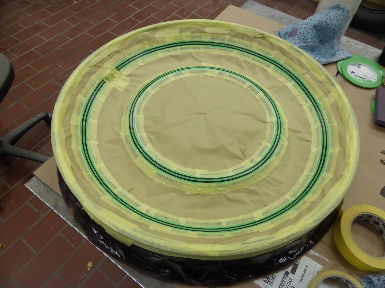 k-P1040515.JPG (133.79 KB) k-P1040515.JPG (133.79 KB)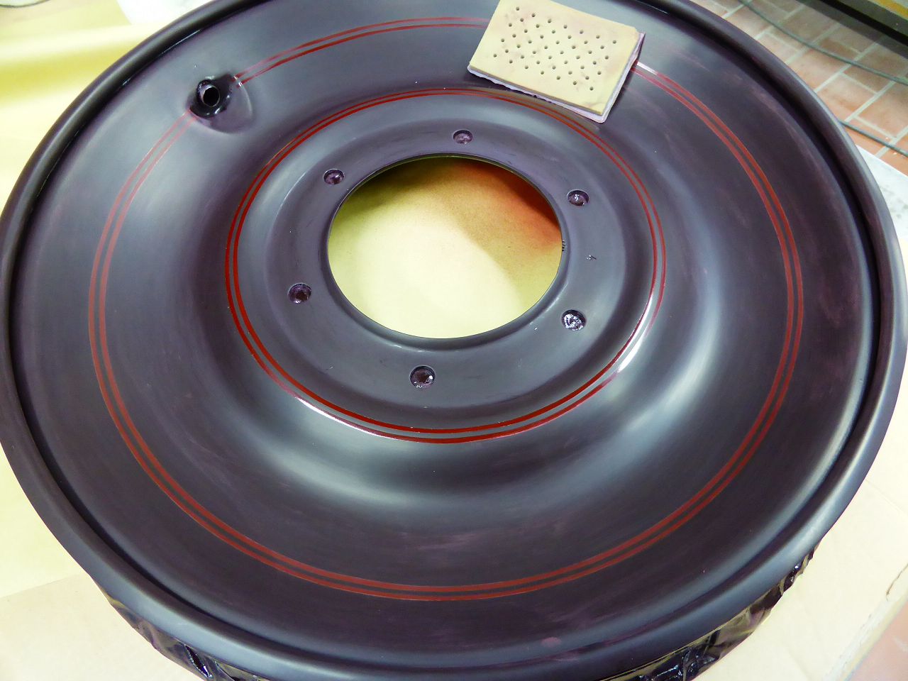 k-P1040516.JPG (165.45 KB) k-P1040516.JPG (165.45 KB)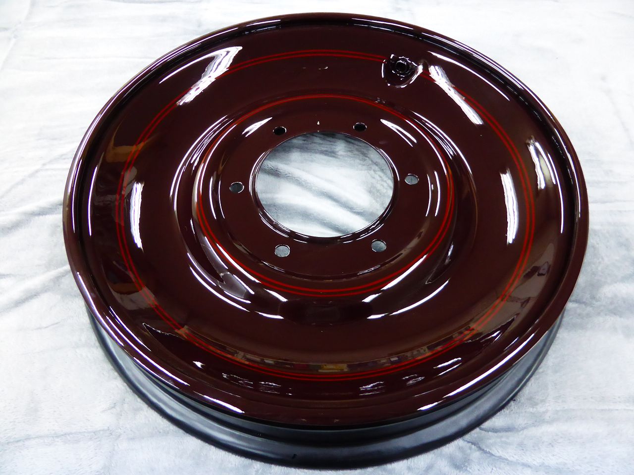
Posted on: 7/12 13:43
|
|||
|
||||
|
Re: Adding vent hole to vacuum fuel tank
|
||||
|---|---|---|---|---|
|
Home away from home
|
David,
What do you think? Yes, of cause I have this bad casting piece. With your description I was able to locate the two valve seats on my sketch drawing. Unfortunately, I didn't pay any special attention to these two seats during the restoration because I wasn't aware of this problem. Is there a way to check whether these valves are ok? I blew hard on the vent valve and it seemed to be tight. Do you know if the spare part you wrote about is still available? Karl
Posted on: 7/5 12:39
|
|||
|
||||
|
Re: Adding vent hole to vacuum fuel tank
|
||||
|---|---|---|---|---|
|
Home away from home
|
David,
could this problem also occur with my 1924 Vacuum Tank?? However, in this discussion I still don't understand exactly which brass seats we are talking about here. I completely rebuilt my vacuum tank and installed the repair kit. Only I couldn't remove the parts in the top cover (vacuum valve), but I tested it for functionality using negative pressure. Karl
Posted on: 7/4 17:06
|
|||
|
||||
|
Re: Bumper clamps
|
||||
|---|---|---|---|---|
|
Home away from home
|
David, .... is dark red also allowed??
Posted on: 7/4 11:29
|
|||
|
||||
|
Re: 1924 Sport 136
|
||||
|---|---|---|---|---|
|
Home away from home
|
Hi human.. if you mean my last post #94 .... that means, that the link in my post #93 doesnt work ... so I post an other one in #94 this works for me. Hope for all other too.
Karl
Posted on: 6/14 7:49
|
|||
|
||||


