|
Re: 1 wire alternator confusion
|
||||
|---|---|---|---|---|
|
Home away from home
|
Hi Dave, thanks for the detailed response. 
First, an update from my end. I did a basic electrical test: I charged the battery then let it sit for a few hours. Before I put it in the car it was a 12.8V, a full charge. I started the car and immediately check the voltage across the battery, 14.8V at high idle. Then I drive to the shop about 10 min. Checked the voltage across the battery again at low idle, 14.8V. Then shut off the car, and about an hour later (I returned to the shop to drop off tires)
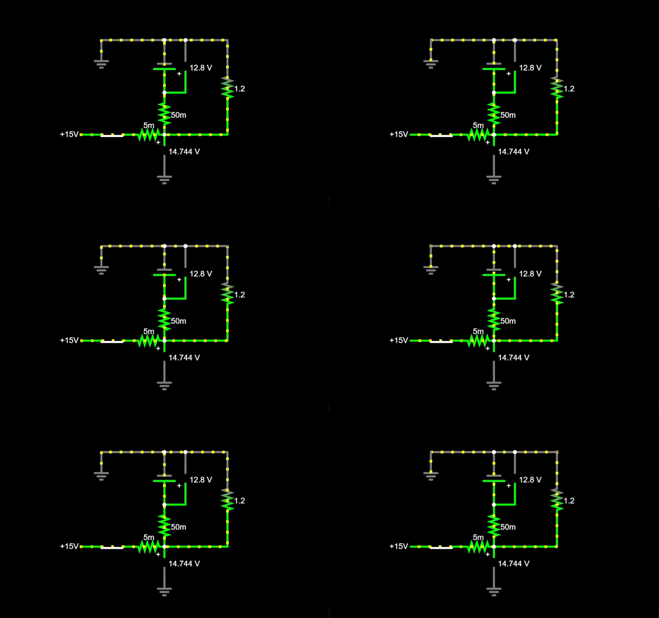
checked the battery voltage again, 12.3V. Only parasitic loads are the clock (probably 10mA average) and the alternator (which is hopefully not doing anything). Given that the battery is 7 years old and sat discharged for about 4 years, I know it's junk and am getting a new one. What's strange is the battery voltage going down when the charging system was obviously working. I will install a voltmeter at some point to verify there's no intermittent issues. Electrically it's not possible for a "charging voltage" to bridge a battery and the battery to still discharge during that time. The only way this could happen is for more energy to be drawn from the battery starting the car twice in 15 mins than was put back in by charging in the same time. However given the condition of the battery and the 50-degree weather this may well be possible. I actually made a GIF of this, the 15V is the alternator, the battery is in the middle (50mΩ internal resistance), and small load on the right. Two voltage readings are shown. This is roughly the current path you would expect with a properly functioning battery and alternator.
I tested some lamps and for low power (<20, say) lamps candlepower lines up well with wattage. Hence an 2CP indicator light I would expect to have about 50Ω resistance in operation, and in parallel with a 10-ohm resistor that's 8.3Ω, at 12½-14½V that's about 1½ amps. I wonder whether the Olds designers were aiming for a minimum of 1 amp current (assuming your Olds was 12V)? I think I'll buy a 10Ω ballast resistor like this and see if that improves things.https://www.digikey.com/en/products/detail/te-connectivity-passive-product/SQBW2010RJ/2365592 
For Terminal 2, from what I understand you don't need to connect it to anything because unless there's a voltage source to it it will sense internally. Generally you'd want to have it connected to near where most of your loads branch off, but unless you're pulling 50+ amps thru 10ga wire or something, the voltage shouldn't even be that different. (FYI, my voltage drop calculator estimates .7V drop for 5 feet 10ga 50 amps.) In our cars, probably it would be best to just use thicker wire in the first place, if the sense terminal were actually needed for proper charging. As I understand, it's mainly for cars with the battery in the rear but the alternator in the front.
Good talk here!
 P.S. I don't know why none of my line breaks are showing up. I added paragraph signs to help. P.S. I don't know why none of my line breaks are showing up. I added paragraph signs to help.Attach file:  2022-12-08 18-44-27 (1).gif (375.86 KB) 2022-12-08 18-44-27 (1).gif (375.86 KB)
Posted on: 2022/12/8 20:37
|
|||
|
'55 400. Needs aesthetic parts put back on, and electrical system sorted.
'55 Clipper Deluxe. Engine is stuck-ish. |
||||
|
||||
|
Re: 1 wire alternator confusion
|
||||
|---|---|---|---|---|
|
Webmaster
|
One note on running a 3-wire without anything attached to the voltage sensing terminal, if that is not hooked up, that alternator is going to be outputting at max all the time, which can overcharge your battery. You at least want to pigtail that terminal back to the bat terminal on the Alt so it can read the bat voltage.
Usually, in GM products where that 10Si was used, the voltage sensing terminal was connected to a wire that was connected near a junction point in the main harness. This was done so its reference voltage was read nearer the load center vs. right off the alternator output. If you don't have the terminal connected, you're going to see very high voltage, which may lead to a cooked battery or the regulator in the alternator having a shorter-than-expected life expectancy.
Posted on: 2022/12/15 9:50
|
|||
|
-BigKev
1954 Packard Clipper Deluxe Touring Sedan -> Registry | Project Blog 1937 Packard 115-C Convertible Coupe -> Registry | Project Blog |
||||
|
||||


