 Charging Circuit.JPG (67.88 KB)
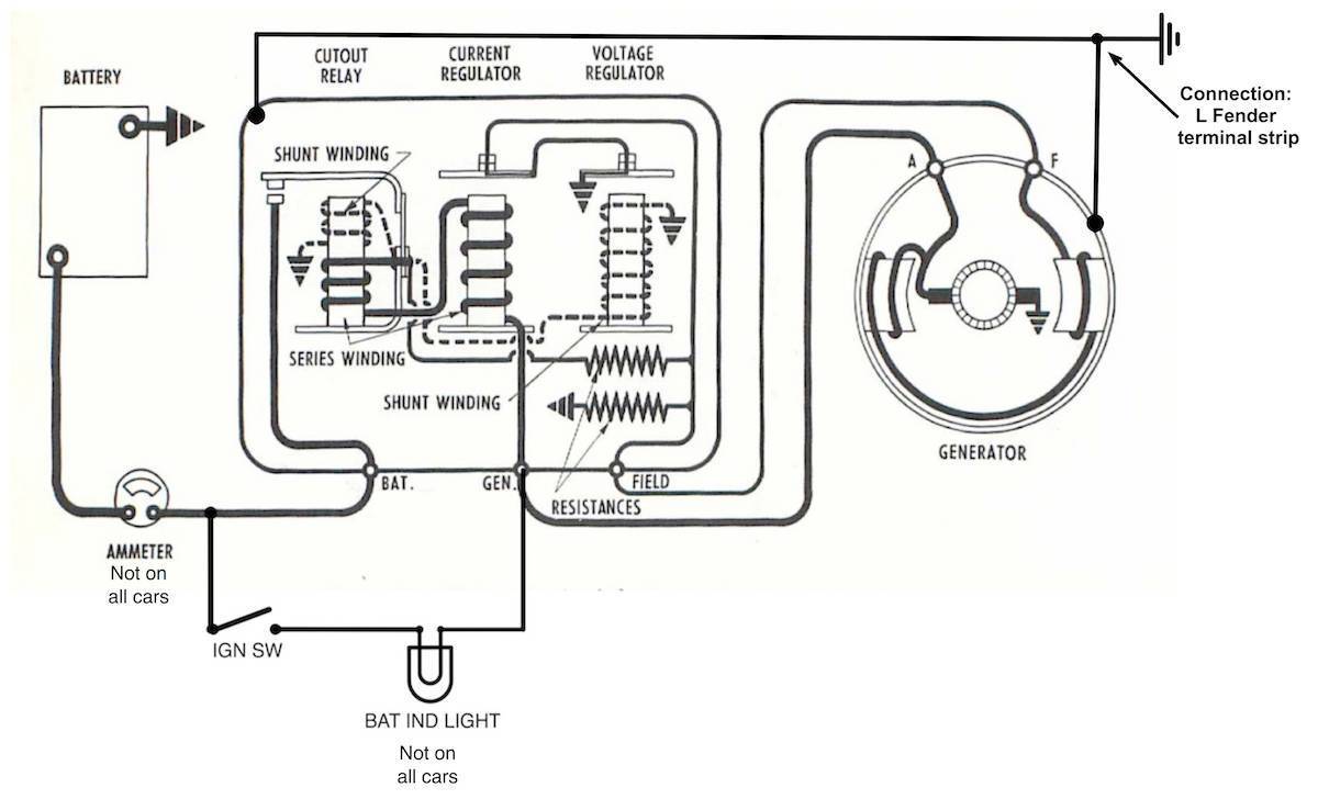
|
Re: Solid State Voltage Regulator
|
||||
|---|---|---|---|---|
|
Home away from home

|
If you simply polarize the regulator it will work either way. There are no diodes in it. However, I think the windings differ in direction according to polarity and that follows the left hand rule for magnetic field.
However, I never deviated from as built and the starter motor is DC and I don't know if it will run backwards.
Posted on: 2022/4/5 17:45
|
|||
|
||||
|
Re: Solid State Voltage Regulator
|
||||
|---|---|---|---|---|
|
Forum Ambassador

|
The stock starter motors -- in fact all stock Packard motors -- will always turn the same way regardless of polarity because they are internally connected so the armature and field coils are always in the correct orientation for a specific direction. If the polarity is reversed they still turn the correct direction because both the field and armature are also reversed at the same time with the polarity change so the magnetic fields, while opposite, are still in the correct orientation for turning a specific direction. This can be observed by remembering all the cars which accidentally had batteries connected backwards with a negative ground. They still started and ran with the main issue being most would no longer charge properly because the generator was now incorrect.
If the car has been upgraded to one of the mini or hi torque starters with a permanent magnet field those will turn backwards if polarity is reversed. Also, any other modern PM field motor that might be installed will be backwards.
Posted on: 2022/4/5 18:05
|
|||
|
Howard
|
||||
|
||||
|
Re: Solid State Voltage Regulator
|
||||
|---|---|---|---|---|
|
Home away from home

|
Howard, what is the type of voltage/current output of the arm and field wires not including the regulator?
I would assume just some unsteady DC voltage between the two.
Posted on: 2022/4/6 8:31
|
|||
|
'55 400. Needs aesthetic parts put back on, and electrical system sorted.
'55 Clipper Deluxe. Engine is stuck-ish. |
||||
|
||||
|
Re: Solid State Voltage Regulator
|
||||
|---|---|---|---|---|
|
Forum Ambassador
|
The maximum output of an unregulated generator depends on the windings and varies with the brand and model of generator. The ARM wire gets the full output, the FIELD wire handles relatively little current as it only carries what the field windings need to provide the changing magnetic strength to the field shoes to regulate output to spec. This is evidenced by the ARM wire usually being a 10 ga and the FLD wire a 16 ga.
A standard postwar 6v automotive generator such as the type Packard specified can produce a maximum voltage in the low teens and a current approaching 60 or so amps. The generators when installed were typically regulated down to a max voltage out of around 7.5v and amps in the range of 35-45. The exact numbers varied by car model and brand of generator/regulator. A constant maximum output will produce enough heat to melt the solder connections in the generator so can only be obtained for a short time. One of the tests on non charging systems to prove if a generator or regulator is most likely at fault is to briefly ground the field wire. This will force a properly working generator to go to maximum output. If the voltage being measured across the battery when the ground connection is made jumps up by several volts it usually proves the generator is working and regulator is at fault. If there is no change then usually it is the generator causing the issue. There are "heavy duty" 6v generators and regulators which were sometimes used in commercial vehicles. Other mfgs routinely used them on cars with AC because of the extra current draw of the blower motors but Packard did not feel the need for them. Those would be regulated to the same voltage range but amps out was usually somewhere in the 55-60 range. A standard 12v generator would have max voltage out in the high teens to low 20s but the max amps out is roughly the same as the 6v model. Regulated output is spec'd at around 13.6v and 30 or so amps.
Posted on: 2022/4/6 9:29
|
|||
|
Howard
|
||||
|
||||
|
Re: Solid State Voltage Regulator
|
||||
|---|---|---|---|---|
|
Home away from home
|
From the literature archive on this site, this service literature from Auto-Lite has a detailed description of how the 3 element regulators work.
https://packardinfo.com/xoops/html/downloads/AutoliteGenerators.pdf
Posted on: 2022/4/6 11:57
|
|||
|
||||
|
Re: Solid State Voltage Regulator
|
||||
|---|---|---|---|---|
|
Home away from home

|
That’s all great information and much appreciated as it gives a wider view of the functionality of a mechanical regulator but not directly related to this thread!
Posted on: 2022/4/6 12:04
|
|||
|
||||
|
Re: Solid State Voltage Regulator
|
||||
|---|---|---|---|---|
|
Home away from home
|
Actually Don I'm going to respectfully disagree with you there. For a regulator design that can properly switch between positive and negative ground (or adapt a design from positive to negative ground as we are doing), it's necessary to understand the complete electrical flow of the charging system, and Howard had corrected some erroneous assumptions I had made. Likewise, BDeB, thank you for posting that link. I had not seen that in the literature archive and it was much more helpful than other explanations I had found online.
Howard, considering that the armature wire would be negative relative to ground in a positive ground system, would the field wire also be negative, or would it be positive? Or AC current?
Posted on: 2022/4/6 16:43
|
|||
|
'55 400. Needs aesthetic parts put back on, and electrical system sorted.
'55 Clipper Deluxe. Engine is stuck-ish. |
||||
|
||||
|
Re: Solid State Voltage Regulator
|
||||
|---|---|---|---|---|
|
Forum Ambassador
|
The generator is capable of either polarity as an output. It needs to be polarized in the correct orientation when first installed in a car or when disconnected and removed, worked on and reinstalled. It is suggested repolarizing be redone when any major component is replaced. Polarizing is done by having everything hooked up, engine and key off, and then momentarily shorting the BAT and ARM terminals on the regulator together. That action puts a high current surge directly thru the generator which partially magnetizes the field shoes. From that point on the generator relies on the small residual magnetic field having enough magnetism to enable initial charging when the engine is started. Polarity out will be dependent on how the N and S poles were aligned during the polarizing.
With the small residual magnetism, when the generator starts turning it will be able to produce a very low current and voltage which is enough to bring in the cut out coil in the regulator via the shunt winding. Once those contacts close battery voltage is then fed into the generator which strengthens the field enough that the generator starts producing a normal output which is then fed back out and regulated to spec by the other two coils in the regulator. Not having the correct residual magnetic field orientation is the reason most systems fail to charge after a battery is accidentally installed backwards. Of those that do work and manage to start putting out a high enough incorrect polarity, serious battery damage usually results if it goes on long enough.
Posted on: 2022/4/6 17:10
|
|||
|
Howard
|
||||
|
||||
|
Re: Solid State Voltage Regulator
|
||||
|---|---|---|---|---|
|
Home away from home
|
Howard, as usual, thank you for the helpful info. I'm going over Don's design again to double check polarity things.
Quote: With the small residual magnetism, when the generator starts turning it will be able to produce a very low current and voltage which is enough to bring in the cut out coil in the regulator via the shunt winding. Once those contacts close battery voltage is then fed into the generator which strengthens the field enough that the generator starts producing a normal output which is then fed back out and regulated to spec by the other two coils in the regulator. However, this is slightly incorrect. The cutout relay on the VR completely disconnects the generator from the battery, so at least when the generator voltage is low, it is completely self-energizing, and it continues to self-energize when connected to charge the battery.
Posted on: 2022/4/16 18:44
|
|||
|
'55 400. Needs aesthetic parts put back on, and electrical system sorted.
'55 Clipper Deluxe. Engine is stuck-ish. |
||||
|
||||


.jpg")


