|
Re: Wiring Diagram for R-6 Overdrive
|
||||
|---|---|---|---|---|
|
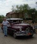
Home away from home

|
As far as I know, no Packard had R7 or R10 overdrive and I had thought that the last year for R6 was 1939.
Posted on: 2021/5/15 15:17
|
|||
|
||||
|
Re: Wiring Diagram for R-6 Overdrive
|
||||
|---|---|---|---|---|
|
Home away from home
|
Hi Don...It seems that this owner purchased an R-6 from one of our suppliers and installed it in his 41-110. It works fine as a three speed, the question is what is necessary shift it into and out of overdrive. Ernie in Arizona
Posted on: 2021/5/15 15:55
|
|||
|
Caretaker of the 1949-288 Deluxe Touring Sedan
'Miss Prudence' and the 1931 Model A Ford Tudor 'Miss Princess' 
|
||||
|
||||
|
Re: Wiring Diagram for R-6 Overdrive
|
||||
|---|---|---|---|---|
|
Home away from home
|
I think the vintageautogarge.com reference was covering the R6-7 differences to the R9-11, and mentions the marks that used both/either an R6 of R7. When they mentioned the years of application I think that was a general statement, else there would be one statement for each mark.
In the aircraft fuel control business we have to ‘bookkeep’ the cycle time between the software making a decision, the output driver awaking, and finally the ‘dumb mechanical system’ component moving (you should hear what the component engineers say about the software people). The time you mentioned is 25ms, so I would say that the time for the DMS to respond to the loss/application of power. There’s also some dimension that the DMS has to move before the contacts that short the ignition points move to the open state. I’m surprised the latency would be stated. How would the dealer mechanic deal with that information? BDeB added that the ’39 had a mechanical ‘block-out’ cable, so we can conclude that the OD Ernie will work on will have that feature, but unless the car was originally equipped with an OD said cable will need to be installed in the car. Ernie adds that an R-6 has been installed in the ’41 110 he’s working on. I still haven’t found any information that senior cars had the newer OD design, while junior cars retained the previous design, so it may be a Frankenstein car. Unless there is an external marking to confirm the design: If the OD is out of the car I think step one is to confirm whether the OD is in fact an R-6 design (it really matters when the electrical controls are added later). With the cable lever in the ‘enable OD operation’ position (cable in), what if the gear ratio was determined in high gear (1:1, not a big challenge), and then the solenoid was powered with a simple jumper. If it’s an R6-7, then the ratio should still be 1:1. If it’s other than 1:1 it’s not an R6-7. If the OD is already in the car, and the cable is installed, one short test drive in ‘forward’ only would confirm the OD is actually OD’ing. Without an electrical system if the OD changes the gear ratio it must be an R6-7 design and the fun with wires can begin. Once the OD has proven that it works, I would stop the car and pull the cable out. And, by the way, have the cable pulled out when you’re first backing out of the shop . . . . There’s no reverse lock-out yet! Once pinned down as to the model of OD is in the car. Ernie either spearheads getting all of the correct OEM parts (switches and brackets) together, complete with some cotton covered wire to lash the whole thing together, or hide a system made of modern components. The important part is the switches are likely different for the R6-7 design (need to confirm this . . . parts book?). To me it looks like the logic of the solenoid side of the kickdown and the reverse lockout, is opposite of those for the R9-11 design. The ignition cut-out appears to be the same. So a good first question might be, “Is there an external marking that identifies the OD design . . . like is R-6 cast into the housing?” If there is a cable already in the car, and it’s hooked-up, call the owner and tell him that he should not push the cable in. Have him write it on a piece of paper and tape it to the dash. dp
Posted on: 2021/5/15 16:10
|
|||
|
||||
|
Re: Wiring Diagram for R-6 Overdrive
|
||||
|---|---|---|---|---|
|
Home away from home
|
I have an R6 lockout cable but just sold the kickdown switch.
Posted on: 2021/5/15 17:08
|
|||
|
||||
|
Re: Wiring Diagram for R-6 Overdrive
|
||||
|---|---|---|---|---|
|
Home away from home
|
If it is an R6 it will say it somewhere on the overdrive case. The solenoid is much smaller than the all-electric units, and there will be no provision for a governor. The unit upshifts at about 30 by means of flyweights incorporated within. Of course the lockout lever needs to be pushed in and the driver has to lift his foot momentarily for the shift to complete. The unit will fall back out of overdrive on its own at about 20.
Any old push-pull cable will work for the lockout as there is no need for for any electrical connection. Just make sure it will move the lockout lever on the side of the case through its full throw. There is no need for electrical lockout or manual lockout when reversing as that is taken care of internally by a cam integral with the 1-R shift arm. Kickdown is achieved by energizing the solenoid. Any push-buttton switch will do, or use the top two terminals on a normal R-11 style switch to operate any old relay that will send ,oh, ten amps or so to the solenoid. The only other wire you need is one from the ign terminal on the solenoid to the dizzy side of the ignition coil to burp the engine while the shift takes place. The R6 units work quite OK but the upshift tends to be abrupt when the unit is warm. Be sure to fill it with GL-1 90 gear oil.
Posted on: 2021/5/15 17:55
|
|||
|
||||
|
Re: Wiring Diagram for R-6 Overdrive
|
||||
|---|---|---|---|---|
|
Home away from home
|
Ross can you fill us in on the purpose of the reverse switch in the diagram Howard posted?
dp
Posted on: 2021/5/15 18:05
|
|||
|
||||
|
Re: Wiring Diagram for R-6 Overdrive
|
||||
|---|---|---|---|---|
|
Home away from home
|
I would view it as belt and suspenders in case someone got up to 30 in reverse. I note that it is arranged to pull the pawl out, as in kickdown, during the entire time the car is in reverse. But I still don't quite get the need for it: when reverse is selected the overdrive lockout cage is moved to the rear of the case (just as when one pulls the lockout cable) I have two Studebakers with R6 on the property just this moment and neither of them have a reverse switch.
Posted on: 2021/5/15 18:21
|
|||
|
||||
|
Re: Wiring Diagram for R-6 Overdrive
|
||||
|---|---|---|---|---|
|
Forum Ambassador

|
Here is a bit on the reverse switch. It seems to be kind of like the reverse safety switch they added to the R9 in 47-48 to kill all OD power to ensure some problem in the OD electrical did not keep the unit engaged when reverse was selected. On the R9 that was an issue.
Since the R6 centrifugal clutch apparently engaged OD as soon as it reached 25-35 mph and did not need the solenoid, I would guess the clutch going slower than that speed knew to pull the pawl and drop out of OD. Since it was all mechanical possibly if something jammed in the centrifugal clutch the R6 had the same issue as the R9 with the overrunning clutch locking up if trying to move in reverse when OD was engaged. The added reverse switch forced the solenoid to come in and pull the pawl out so it could not be in OD. Anyway that is one theory until something better comes along. Attach file:  reverse switch.jpg (374.34 KB) reverse switch.jpg (374.34 KB)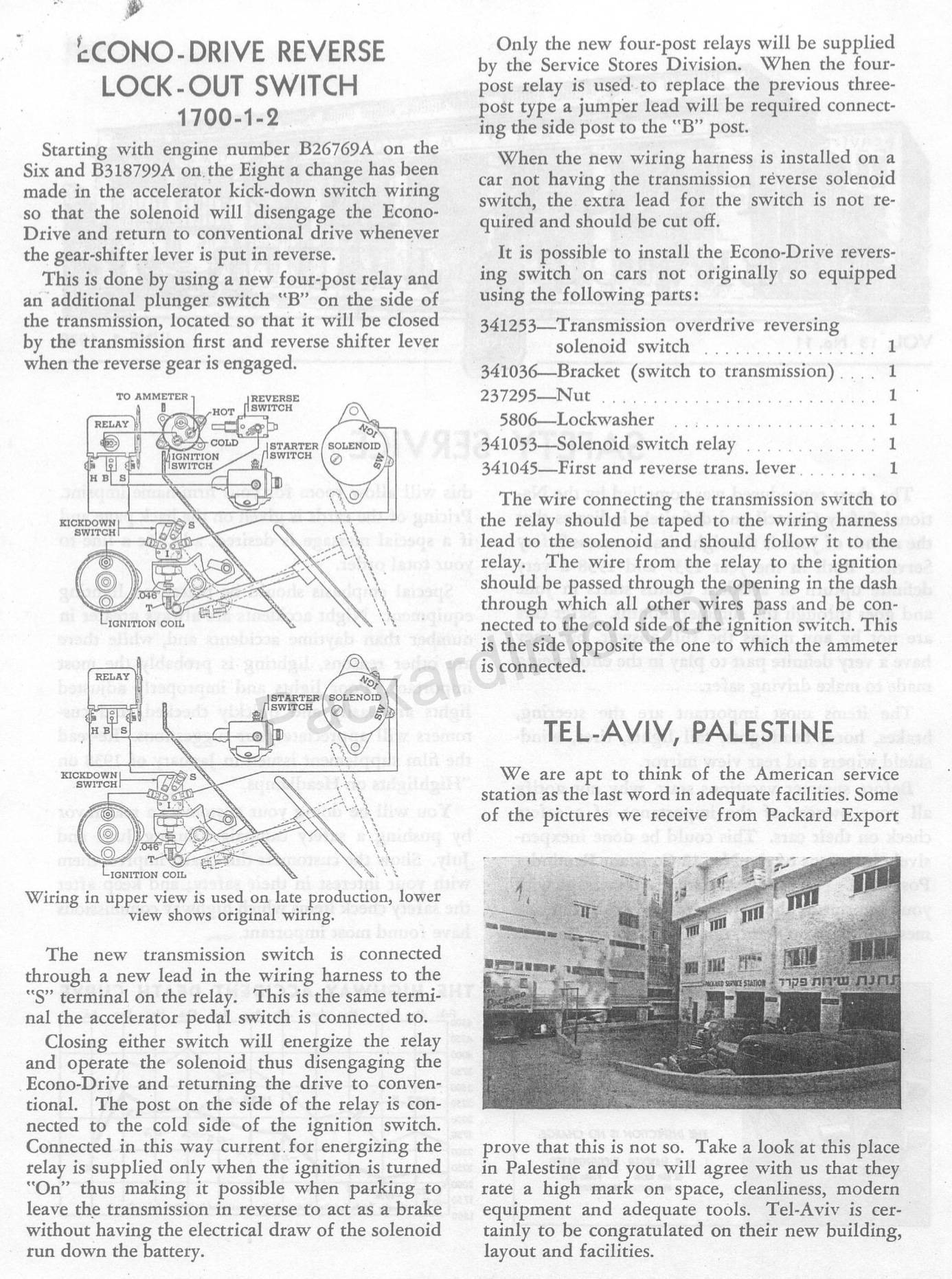
Posted on: 2021/5/15 18:41
|
|||
|
Howard
|
||||
|
||||
|
Re: Wiring Diagram for R-6 Overdrive
|
||||
|---|---|---|---|---|
|
Home away from home
|
Good afternoon all...I am receiving a most interesting education today. Thank you all. I have not seen the car as yet and might not for a week or so. At that point I'll try to post photographs of what we have. Don I might well need that cable when the time comes...Ernie in Arizona
Posted on: 2021/5/15 18:48
|
|||
|
Caretaker of the 1949-288 Deluxe Touring Sedan
'Miss Prudence' and the 1931 Model A Ford Tudor 'Miss Princess'
|
||||
|
||||


.jpg")


