IMG_18571.png (826.57 KB)
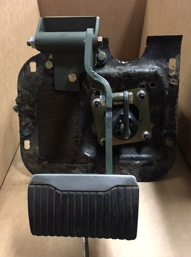
|
Re: Treadle Vac Conversion
|
||||
|---|---|---|---|---|
|
Home away from home

|
Hi,
If it works it is very interesting, at the very least. I have one observation, and a couple of suggestions. Looking at the picture of the linkage: Unless there is something I am not seeing, the pedal ratio would be the ratio of the distance from the pedal to the pivot, divided by the ratio of the distance from the booster axis to the pivot, measured perpendicular to the pivot axis. So looking at that picture and eyeballing it, I don't see anything more than 2:1. Could even be less. They seemed to go to a lot of trouble to make the pedal lever longer, but in the process moved the pivot away from the booster axis as well. Maybe i am just looking at it from the wrong angle. I would suggest before you go this route you should: A) Verify how the pedal ratio is calculated and what it actually measures out to. B) Verify the master cylinder diameter they are using. That way you can compare to what you would get with the original setup with an approximately 5/8" master cylinder diameter and a 1:1 pedal ratio. Note - I have never measured the actual diameter of the T.V. piston (really a rod displacing fluid) myself, I have seen it as either 0.655 or 0.625 or even 0.62. Pressure/pound of foot force = 4 X P.R. / 3.14159 / D^2 P.R. = pedal ratio D = master cylinder diameter So for: D = 5/8 and a P.R.=1, you have Pressure/pound of foot force ~ 3.25 for: D = 1 and a P.R. of 4 you have Pressure/pound of foot force ~ 5.09 for: D = 1 and a P.R. of 3 you have Pressure/pound of foot force ~ 3.82 for: D = 1 and a P.R. of 2 you have Pressure/pound of foot force ~ 2.55 Personally, I tried a 1:1 pedal and a Ford Courier dual master system with a small booster that fit just where the TV does, so like 7" diameter. It had a 3/4" cylinder diameter. So for D = 3/4 and a P.R. of 1 you have Pressure/pound of foot force ~ 2.37 it was NOT ENOUGH. Now in the system above, it looks like they moved the booster over so they could fit a bigger booster in there, which would give you more boost/assist than the T.V., so perhaps you would have better or adequate brakes as long as you had vacuum. But if you lost vacuum - not a fun time. Hope this helps!
Posted on: 2022/2/1 21:50
|
|||
|
||||
|
Re: Treadle Vac Conversion
|
||||
|---|---|---|---|---|
|
Forum Ambassador

|
That pedal position looks a lot like what Craig wound up doing -- but maybe a bit more refined in the fabrication because the pedal is still suspended from the top. Can't quite tell exactly what is going on with the second small arm between the pedal and booster with the connection to the booster center being much lower than the takeoff from the pedal arm. Is it a second moving linkage for ratio multiplication?
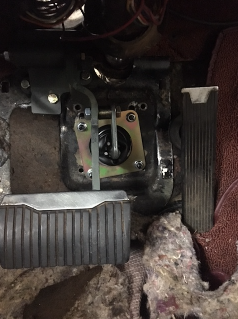
Many felt having the pedal that way moves the pad too far down toward the flat floor and defeated Packards look, feel and ease of use. Not looking anything close to stock is a big deal to some. The original position has the brake pad up and more level with the accelerator so you only needed to rotate your foot over to hit the brake rather than lift your foot and then move it lower. Some who drove Craigs car said it felt awkward at first but they thought they could get used to it. Attach file:  brake.jpg (65.90 KB) brake.jpg (65.90 KB)
Posted on: 2022/2/1 22:00
|
|||
|
Howard
|
||||
|
||||
|
Re: Treadle Vac Conversion
|
||||
|---|---|---|---|---|
|
Quite a regular
|
Quote:
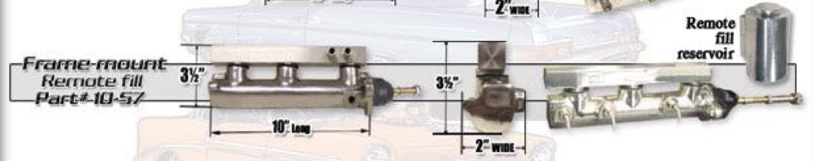
I spoke with the company and they think that it is a 15/16" bore master cylinder . He said that he would check on the pedal ratio and I will call back tomorrow. He thinks it is a 4:1, but I personally don't see how. I think a 3:1 would be pushing it looking at the picture. Another option I thought of would be to use a 5/8 dual master cylinder with a remote mounted booster. I found a dual 5/8 master cylinder that looks to use one master cylinder for the front brakes and one for the rear. I also saw a regular dual remote master cylinder that is also a 5/8 bore. Would either of these work with the pedal in the factory location since the bore is similar to the Treadle-Vac? I would also add a booster to the system, but I want to be able to stop without it. Links to 5/8 bore dual master cylinders: Dual Master Cylinder Kit, 5/8″ bore Tandem Master Cylinder 5/8" Bore
Posted on: 2022/2/2 22:55
|
|||
|
||||
|
Re: Treadle Vac Conversion
|
||||
|---|---|---|---|---|
|
Home away from home
|
The problem with the dual master cylinder is that the formula I put up earlier is not correct in this case, since the force is (roughly) equally applied to each cylinder, the formula would now be
Pressure / pound force = 4 X P.R. / 3.14159 / D^2 / 2 = 2 X P.R. / 3.14159 / D^2 that is, the force is cut in half. So you'd need a P.R. of at least 2 to get back to what the T.V. does. And of course you might not be able to get a booster in there either. For the second one, well I actually purchased one myself to check it out. The main problem is that the stroke of 1.31" is very small in comparison to the T.V. stroke of something around 3". So you could easily run out of stroke. Also that master cylinder is not designed for a booster, and adapting one to it is quite a project in itself. Here's another thread on a related subject: 1953 Manual Brake conversion And this one: Ford Courier Dual Master BTV replacement (experiment)
Posted on: 2022/2/2 23:31
|
|||
|
||||
|
Re: Treadle Vac Conversion
|
||||
|---|---|---|---|---|
|
Quite a regular
|
Thanks for the links. Here is another 5/8 bore dual master that is originally for a 1980’s Volvo. It is designed to be used with a booster. Would this be any better of an option? I couldn’t find what the stroke is on this one compared to the Treadle-Vac.
Link to Master Cylinder: https://www.stockwiseauto.com/dorman-m39641-brake-master-cylinder?fit_id=6059&Year=1987&Make=Volvo&Model=740&gsID=pxf1974760f6059&gclid=EAIaIQobChMIzvyXvPHi9QIVj67ICh1Wlg2DEAQYAiABEgKylvD_BwE
Posted on: 2022/2/3 1:24
|
|||
|
||||
|
Re: Treadle Vac Conversion
|
||||
|---|---|---|---|---|
|
Home away from home
|
That's an interesting find! It has a chance of working. The important thing (as noted by HH56 below) is what is the stroke? Might not know until you get one.
Question: The specs list two piston diameters 0.625 and 0.875. I don't quite know what that means, but that could be some kind of inner proportioning valve. Also, the specs could be inaccurate. In a standard dual master cylinder, the primary piston pushes on the fluid only, and the fluid itself is what pushes on the second piston, unless there is a failure in the primary circuit. How Stuff Works - Dual Master Cylinder If it's anything like a standard-design dual master cylinder, the important spec is the diameter of the primary piston. If that's 0.625", then well worth a try. If it's 0.875", might not be. Also have to find a booster less than 7" diameter that would bolt up. If you want to go ahead and try the 740 Volvo Cylinder, I would be willing to ship you my 7" Ford Courier Brake Booster, which I know fits in there on a 1953 and presumably also then a 1955/56, on the condition that if everything works well you would ship it back. Those Ford Courier Brake Boosters are still somewhat available. What I saw for the Volvo 740 was 8" diameter, which wouldn't fit I am pretty sure. 1981/82 Ford Courier 7" Brake Booster #53-5211 (Autozone)
Posted on: 2022/2/3 10:53
|
|||
|
||||
|
Re: Treadle Vac Conversion
|
||||
|---|---|---|---|---|
|
Forum Ambassador
|
One thing I am curious about with the small 5/8 bore master is the total fluid volume out with the stroke that will be available. On one of the earlier posts where the 3/4 master was tried, a comment that some of the Stude conversions did not allow a full stroke to actuate both pistons in a dual master was noted. I would wonder about that here too -- particularly with any kind of decreased stroke forced by the ratio change.
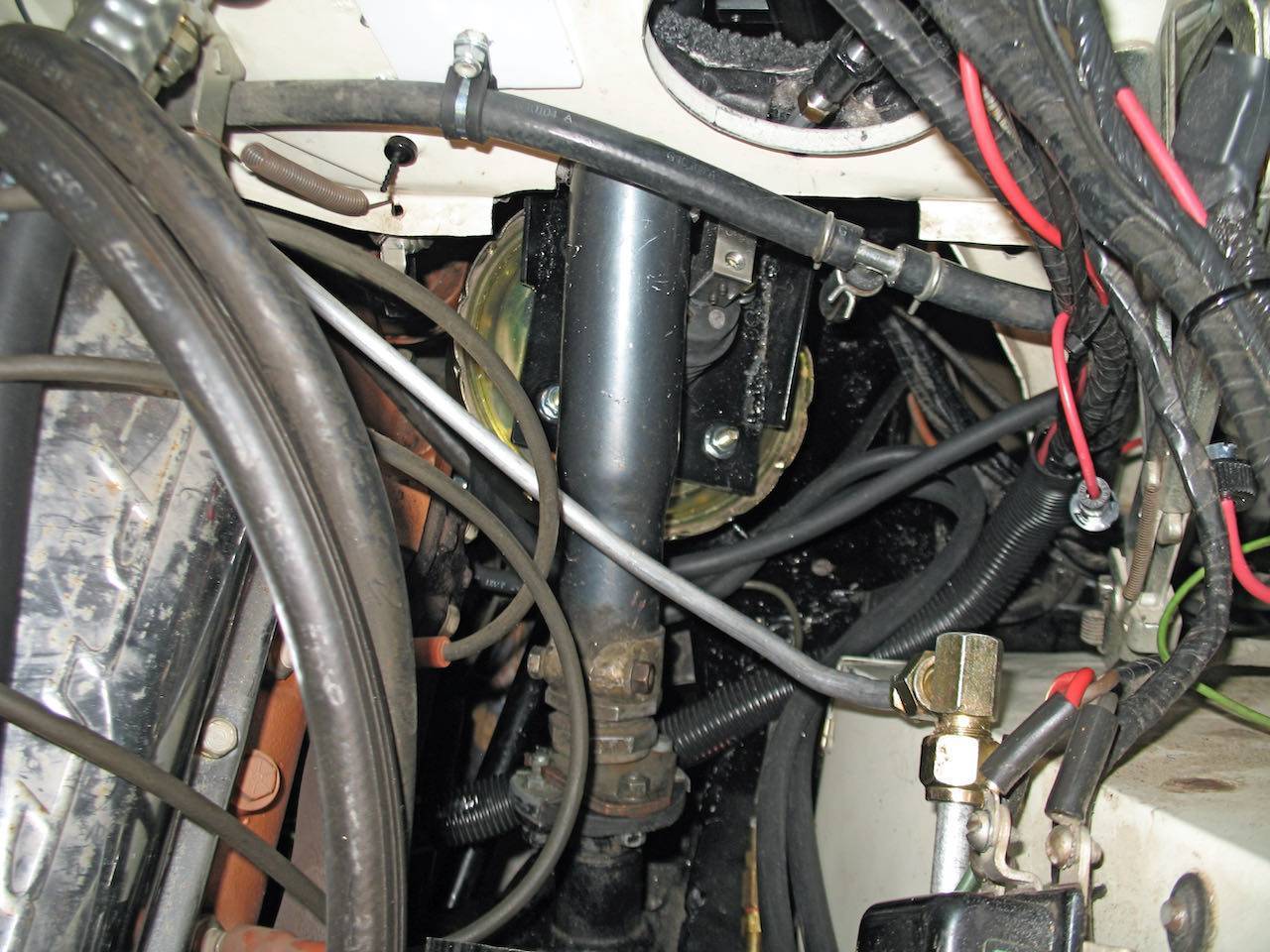
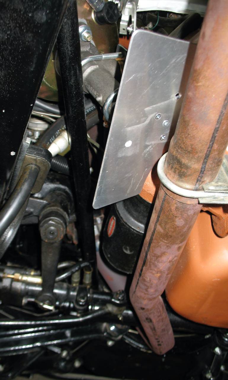
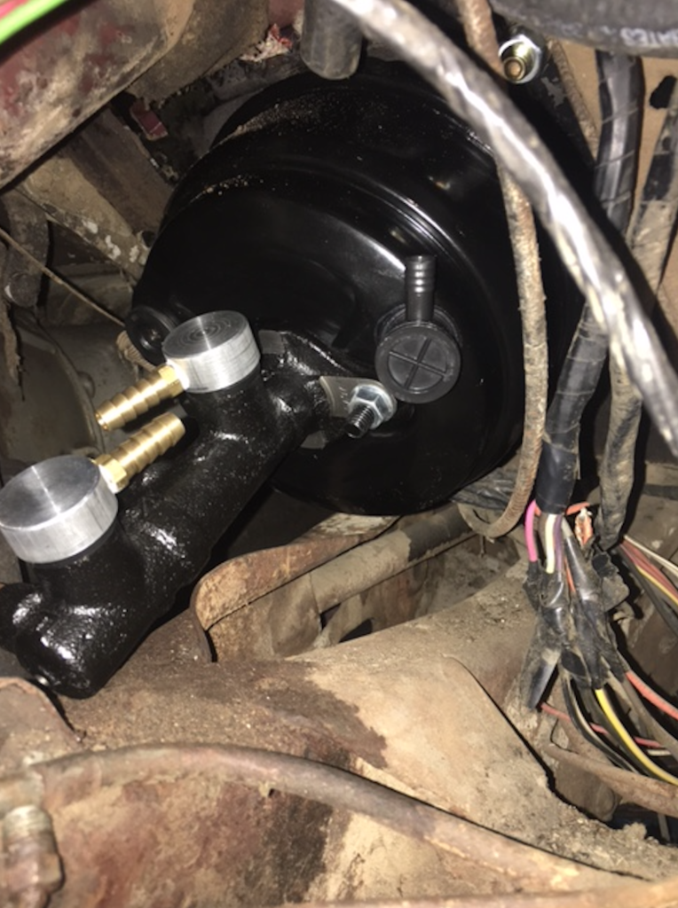
As to volume, during some of my early experiments a crude test measured the BTV output at approx 20ml at full stroke. A properly adjusted drum arrangement should be able to cope with some reduced volume but if any disc conversion is also contemplated then I would be concerned. The decreased stroke was one of the issues I ran into with some of my experiments. To compensate I made extensions to mov the pedal pivot higher and outward. Due to the AC that part was limited but I was able to lengthen the arm to increase the ratio as well as made the arm angled to raise the pedal from the normal location relative to the floor board to get more stroke. That location also requires the foot to lift but at least the pedal pad stayed in the same relative position adjacent to the accelerator -- similar to where a manual brake pedal would be so was not a very noticeable change. If I were able to do any more experiments (age makes that less probable) I would like to redo what I have now because the current arrangement is much too sensitive. What I would like to do is revise the current linkage to use an Electroboost instead of using the vacuum booster now on the car. I currently have the booster and master mounted at a severe angle pointing to the starter and to get the decent ratio, the takeoff and a bellcrank is hidden in the vent opening (vent is still totally functional because of factory AC) with the actuating rod going down to the booster. I would like to mount an Electroboost at the same level as the bellcrank but at 90 degrees parallel to the firewall where it could be hidden under the AC blower or at least be much less visible than the current vacuum booster conversions which use the vent space. The current vent conversion is not possible with AC because the vent is needed. Here are a couple of shots in mockup and in the car. As I mentioned, still a work in progress. Attach file:  IMG_0280.jpeg (94.38 KB) IMG_0280.jpeg (94.38 KB)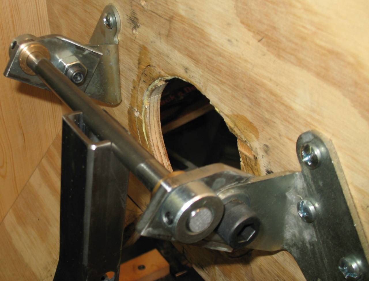 IMG_0285.jpeg (41.44 KB) IMG_0285.jpeg (41.44 KB)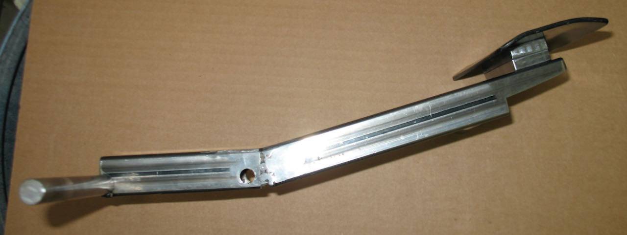 IMG_0300.jpeg (117.39 KB) IMG_0300.jpeg (117.39 KB)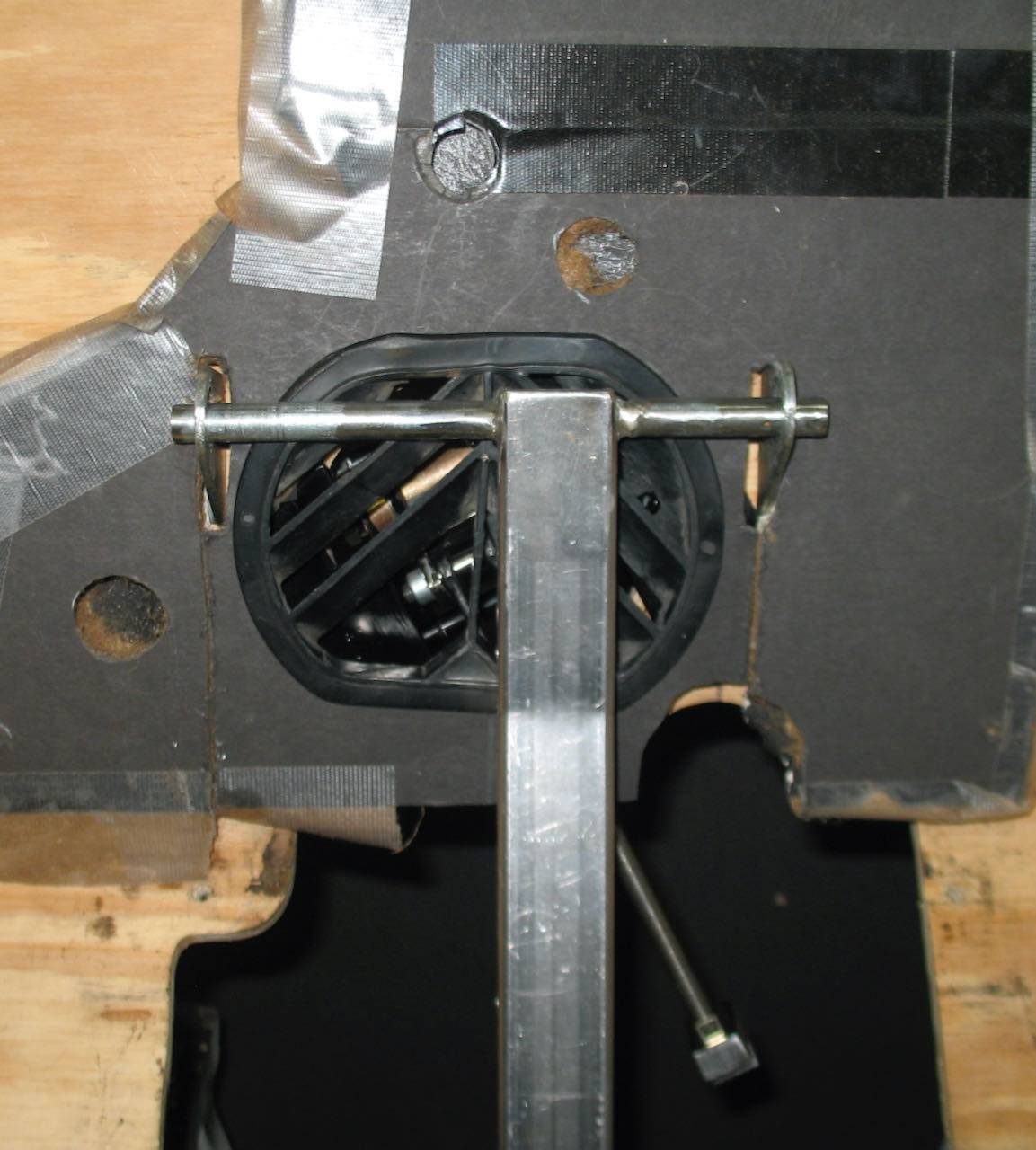 IMG_0292.jpeg (105.67 KB) IMG_0292.jpeg (105.67 KB)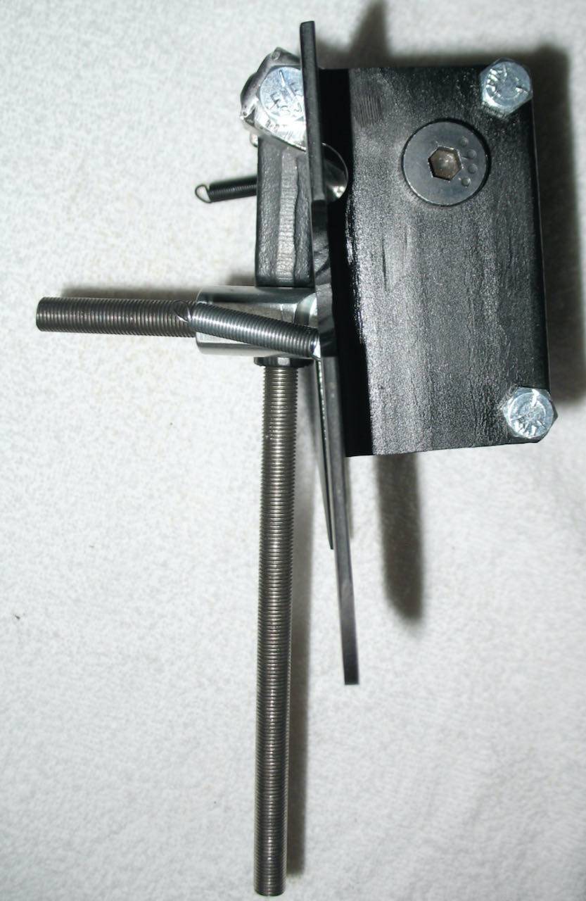 IMG_2514.jpeg (184.32 KB) IMG_2514.jpeg (184.32 KB) IMG_2516.jpeg (217.75 KB) IMG_2516.jpeg (217.75 KB)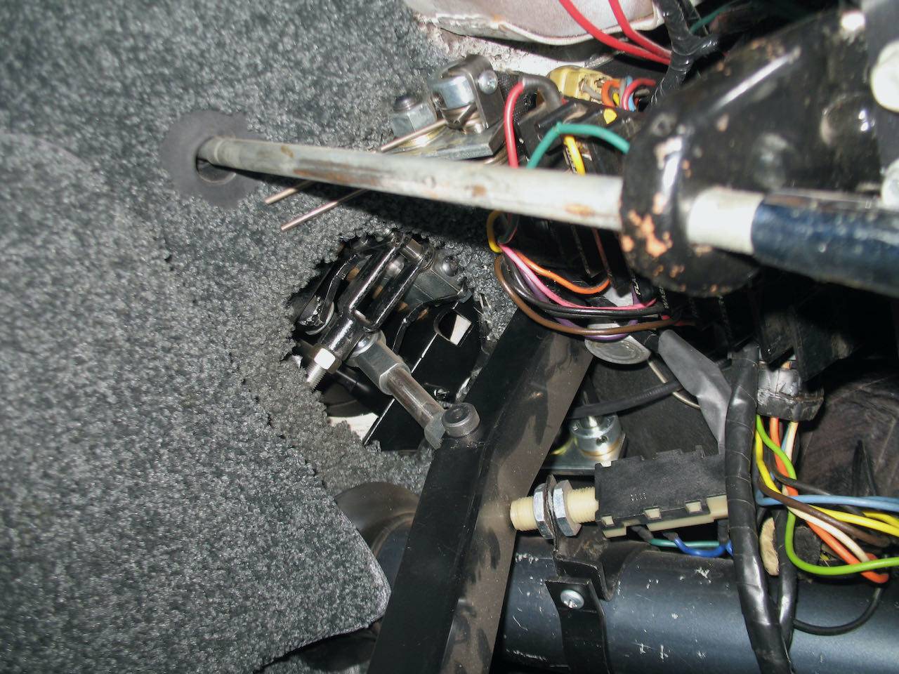
Posted on: 2022/2/3 12:23
|
|||
|
Howard
|
||||
|
||||
|
Re: Treadle Vac Conversion
|
||||
|---|---|---|---|---|
|
Quite a regular
|
Quote:
I called the company and found out that the initial rear of the master would be 5/8 and the front would be 7/8. They said it didn’t matter if the front or rear was attached to the 5/8, but one would be attached to the 7/8 bore. In other words, the 5/8 comes first before the 7/8 from what I understood. Quote:
Is your master cylinder and booster in the stock location? Your set up looks nice.
Posted on: 2022/2/3 14:36
|
|||
|
||||
|
Re: Treadle Vac Conversion
|
||||
|---|---|---|---|---|
|
Forum Ambassador
|
The current booster portion is sort of in the same location but goes off at 90 degrees with the master pointing at and is near the engine. The whole assy is at a very severe angle and was hard to mount so not a good solution -- but it does work and maybe a bit too well because it is very sensitive. Don't have any really clear photos but maybe you can get some idea from these.
I believe with a revision to the bellcrank one of the thinner Electroboost masters could mount parallel to the firewall just above the steering column. It might mount level or at least be at a much lesser angle. Not sure but it might even fit pointing the other direction to be partially hidden under the emergency brake mechanism. If so, that orientation would mostly solve the "mod in your face" situation but which side the ports exit would determine the placement and direction. A revised bellcrank and part of a mount for the master could be built into a sturdy short tube like module which would fit before the first vent section. Being hollow air flow could be maintained. The original short vent tube could reattach to the module and its length could fit into some of the space where the flexible duct is now. Reinforce the firewall with a plate on the inside and bolt thru the firewall and plate to have the module assy cover the vent opening on the engine side. In the AC setup, the module would go in front of the Tee section below the blower. Of course that would take some more design because the blower doesn't have much leeway in where it can move. It might need another mod to the existing AC Tee section to fit on the module and the on/off flapper valve.
Posted on: 2022/2/3 15:09
|
|||
|
Howard
|
||||
|
||||