|
Re: 1940 horn assembly
|
||||
|---|---|---|---|---|
|
Home away from home
|
Check out post #908 at the bottom
https://packardinfo.com/xoops/html/modules/newbb/viewtopic.php?topic_id=2179&forum=10&post_id=87081#forumpost87081
Posted on: 2022/6/7 17:16
|
|||
|
||||
|
Re: 1940 horn assembly
|
||||
|---|---|---|---|---|
|
Forum Ambassador

|
54 is different from the 40 and earlier models and the drawing in post 4 of this thread is accurate as far as the major pieces and how the wire connects to the horn ring.
Main difference between the 47 wheel in the drawing and the 54 is the horn emblem and retaining method is different and screws holding the ring mounting to the wheel is from the front instead of the rear. Basically the 54 wire is soldered to a copper cup that sits on an insulating washer at the end of the steering shaft. The insulating washer supports and keeps the cup from touching ground. When the horn ring mounts, ground is carried by the large spring and 2 spring guides from the steering shaft to one side of the ring. The wire cup is pressed against another piece which is a contact plate isolated from the ring and makes the connection for the other side. Pushing the horn ring tilts it slightly and closes a very small gap between the edges of the two sections to complete the circuit.
Posted on: 2022/6/7 17:19
|
|||
|
Howard
|
||||
|
||||
|
Re: 1940 horn assembly
|
||||
|---|---|---|---|---|
|
Not too shy to talk

|
Screws
Attach file:  B79CD363-BF99-45DD-8C17-2D8B6C255B68.jpeg (148.15 KB) B79CD363-BF99-45DD-8C17-2D8B6C255B68.jpeg (148.15 KB)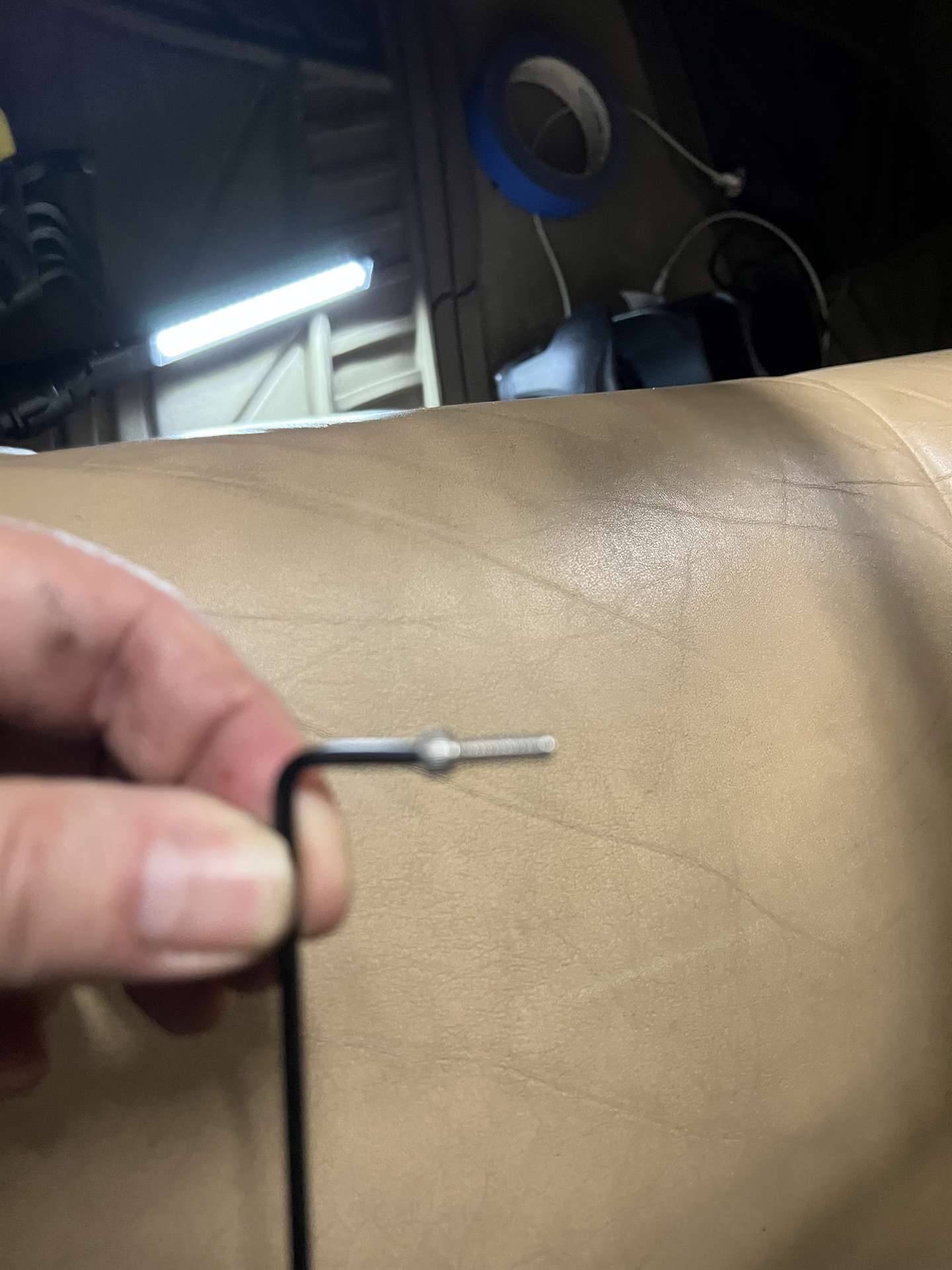
Posted on: 2023/2/10 10:52
|
|||
|
||||
|
Re: 1940 horn assembly
|
||||
|---|---|---|---|---|
|
Not too shy to talk
|
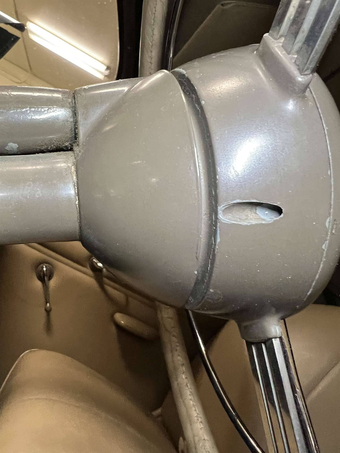
Wiring
Attach file: 0DCEE1E9-CA49-422C-AC4A-620DC1837611.jpeg (223.86 KB)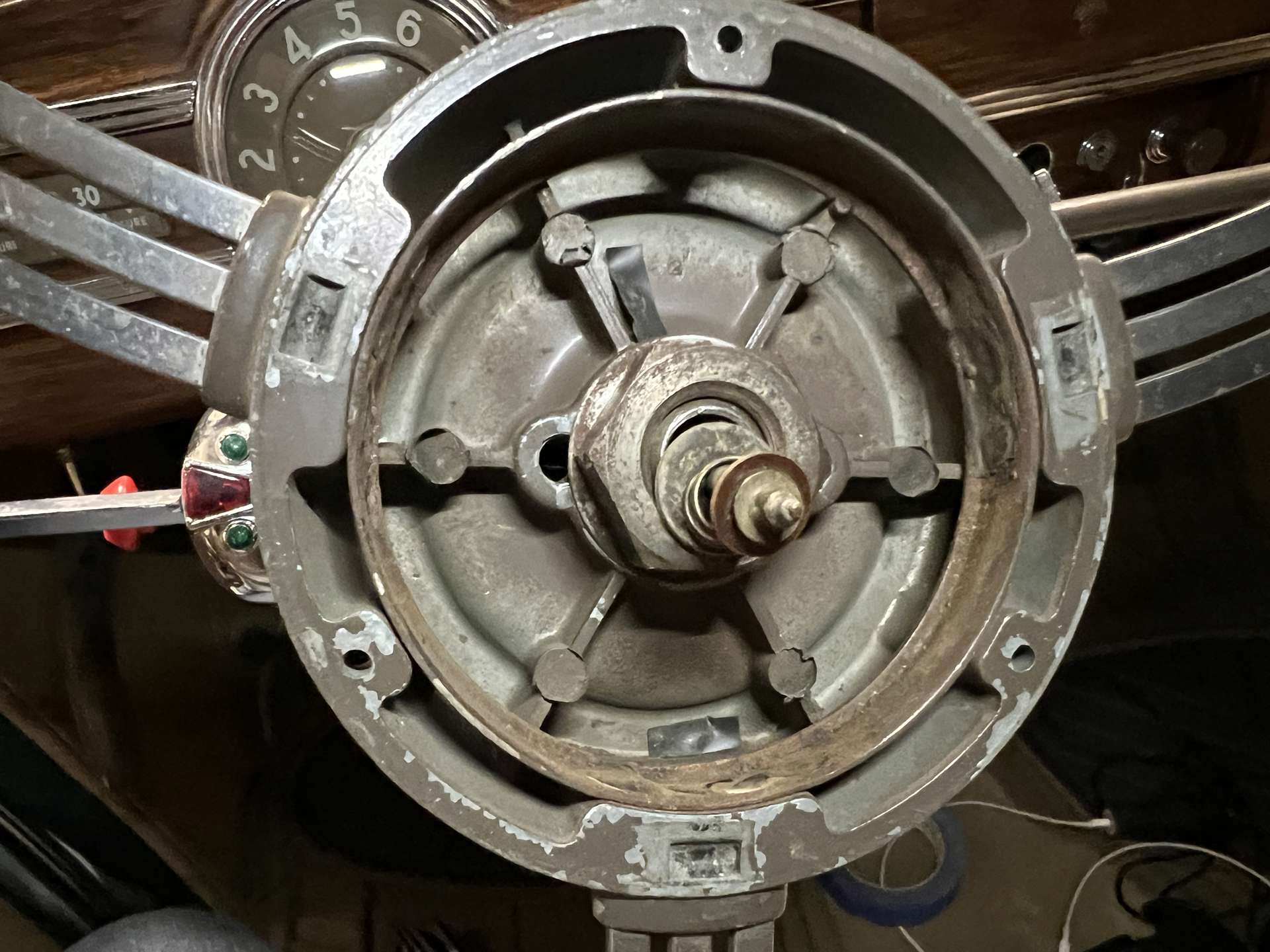
Posted on: 2023/2/10 10:55
|
|||
|
||||
|
Re: 1940 horn assembly
|
||||
|---|---|---|---|---|
|
Not too shy to talk
|
There is a large fiber non-conductive washer first, then a spring, then a small fiber washer, then finally the conductive cap soldered to the end if the wire
Attach file: A12ECC33-77F9-4030-9956-54DD0758D625.jpeg (223.42 KB)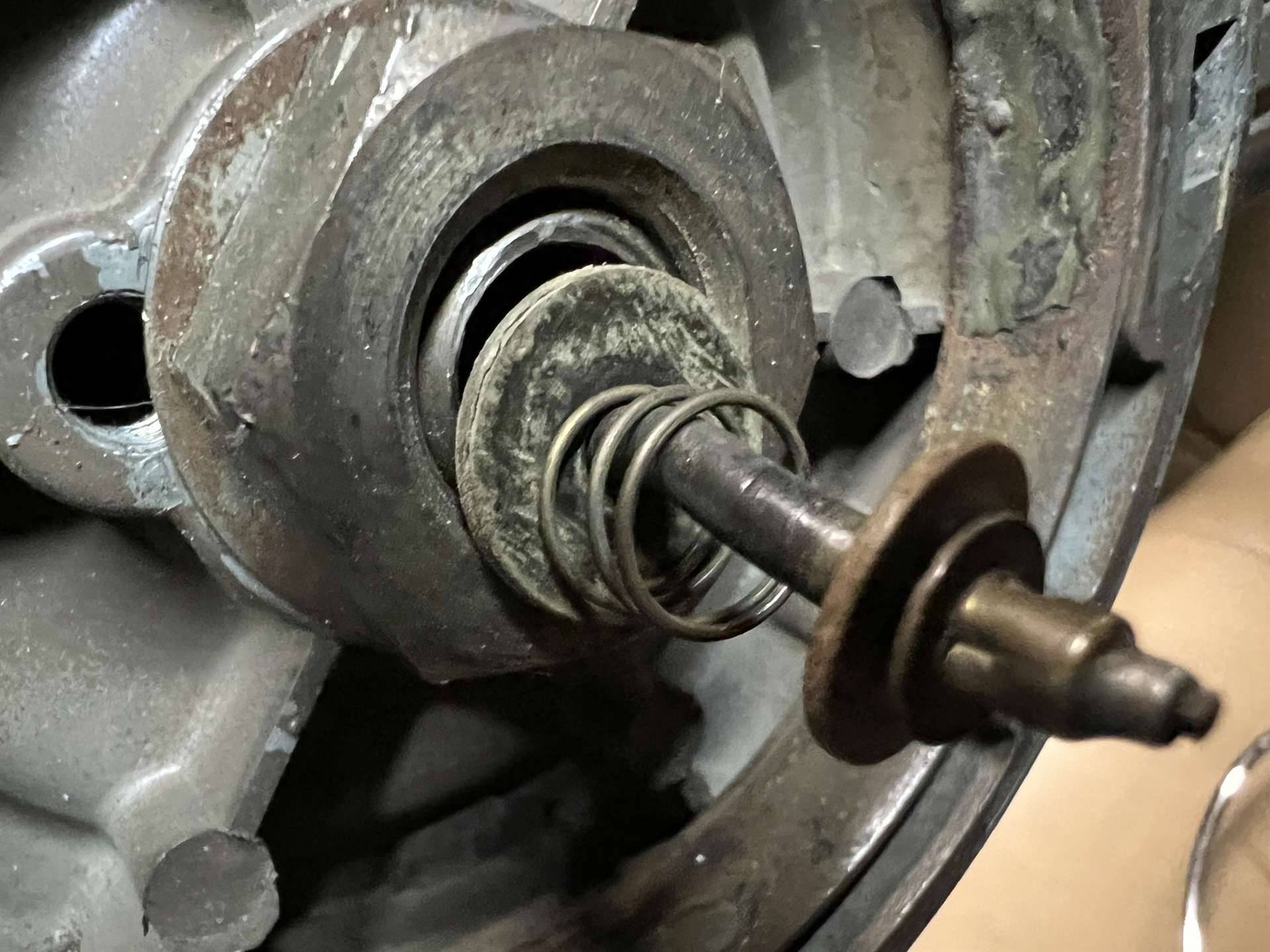
Posted on: 2023/2/10 11:03
|
|||
|
||||
|
Re: 1940 horn assembly
|
||||
|---|---|---|---|---|
|
Not too shy to talk
|
This is the bottom of the horn bar. The bumps are the pivot point and ride in notches in the steering wheel.
Attach file: 6053F159-3A5C-4873-8CF5-1E9039315928.jpeg (135.42 KB)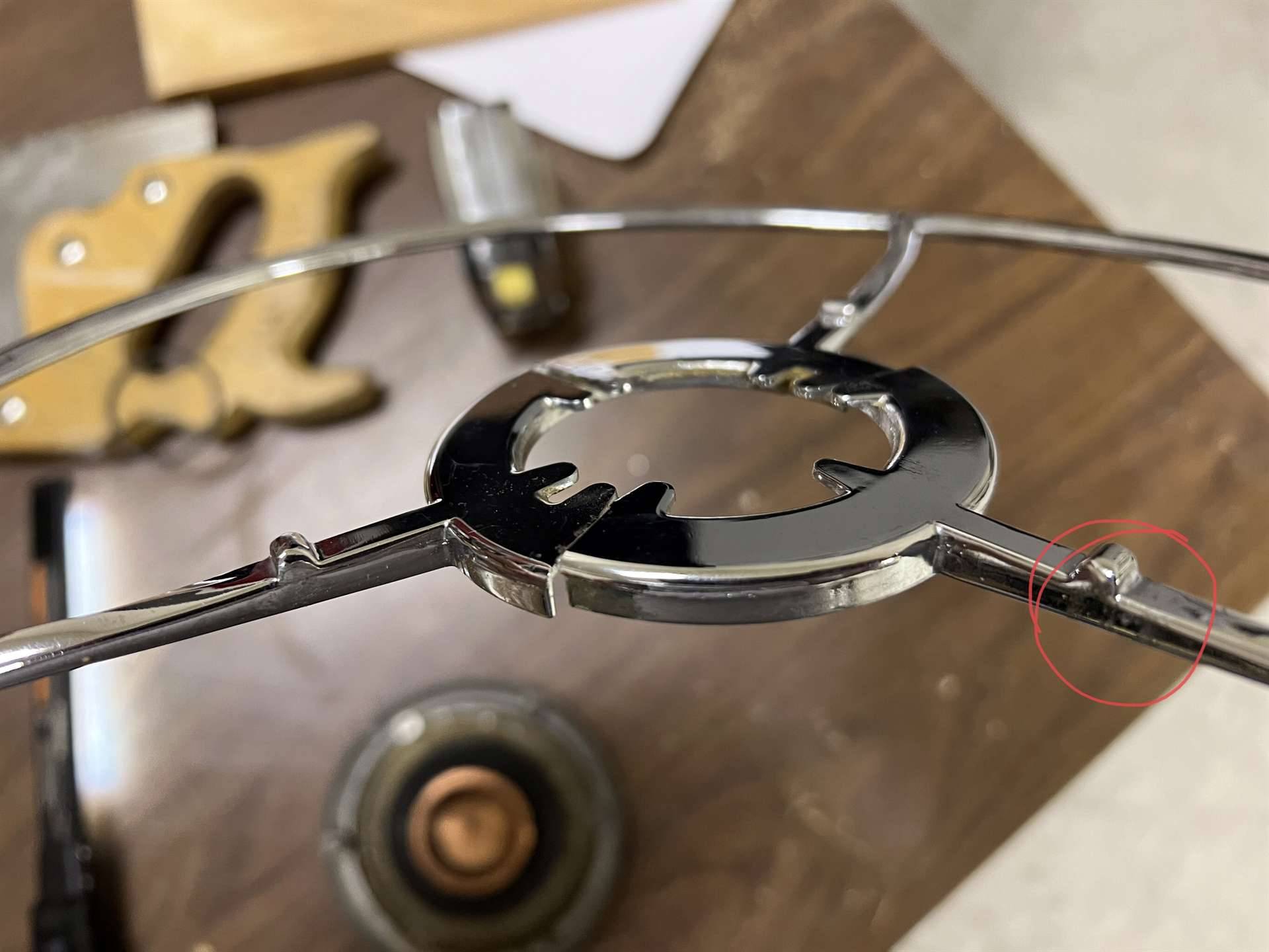
Posted on: 2023/2/10 11:07
|
|||
|
||||
|
Re: 1940 horn assembly
|
||||
|---|---|---|---|---|
|
Not too shy to talk
|
Bottom of the cap with copper conductive dish.
Attach file: 4BD62A48-F2FE-4BFE-BD5A-1BE57512DA19.jpeg (468.57 KB)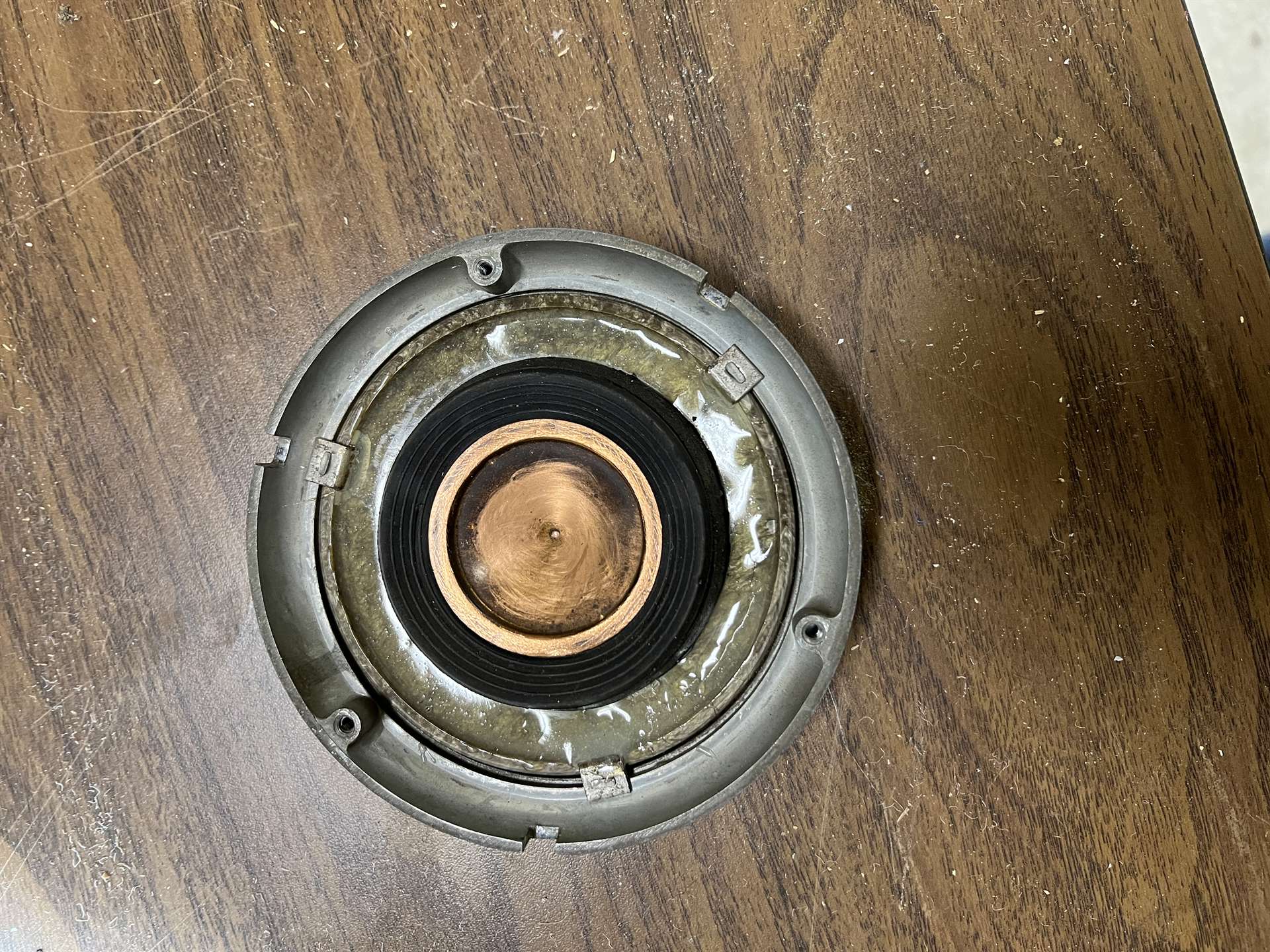
Posted on: 2023/2/10 11:08
|
|||
|
||||
|
Re: 1940 horn assembly
|
||||
|---|---|---|---|---|
|
Not too shy to talk
|
The original foam or rubber gasket/insulator was deteriorating so the horn was going off on its own in the middle of the night. I used a hard rubber plumbing gasket from home depot for the top (well at least the top when the cap is upside down and you are looking at it.
Attach file: B6FD0814-A921-45D6-BDE9-369EE7046ECE.jpeg (288.44 KB)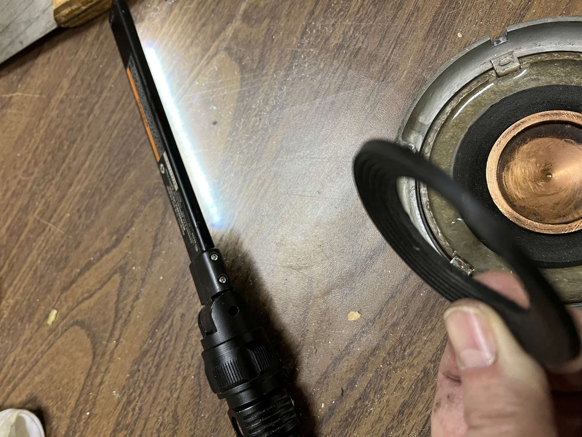
Posted on: 2023/2/10 11:22
|
|||
|
||||
|
Re: 1940 horn assembly
|
||||
|---|---|---|---|---|
|
Not too shy to talk
|
The lower gasket was also from Home Depot plumbing section. It is soft foam and provided the compression when the horn bar is pressed. The combination of the two gives a perfect height and the right amount of recoil or pressure so that the inner part of the horn bar is held off of the cooper bowl, but the touch and travel needed to activate the horn feels right. Honestly I got lucky with the combo.
Sorry I don’t have the packages from the gaskets anymore. The thin hard one is about 1/8” thick. Soft one is around 3/8”. Sorry I did not measure them last night while I had it apart. Attach file: A8548A36-6EFA-4EF0-9E98-1CCD91501239.jpeg (293.56 KB)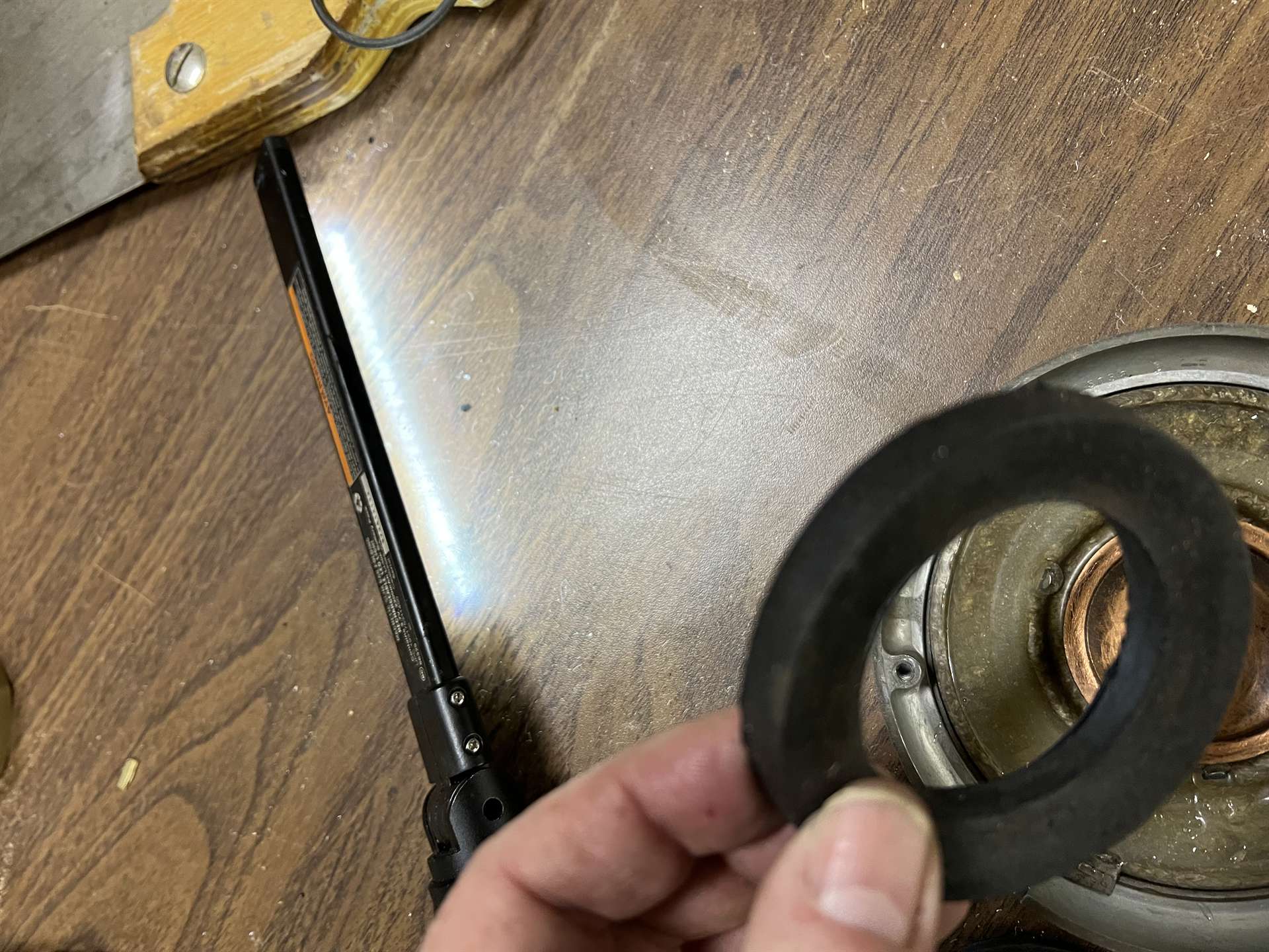
Posted on: 2023/2/10 11:28
|
|||
|
||||


.jpg")


