Hello and welcome to Packard Motor Car Information! If you're new here, please register for a free account.  
Login
Username:

Password:

Remember me


Lost Password?

Register now!
FAQ's
Main Menu
Recent Forum Topics
Who is Online
130 user(s) are online (97 user(s) are browsing Forums)

Members: 0
Guests: 130

more...
Helping out...
PackardInfo is a free resource for Packard Owners that is completely supported by user donations. If you can help out, that would be great!

Donate via PayPal
Video Content
Visit PackardInfo.com YouTube Playlist

Donate via PayPal


« 1 2 3 4 (5) 6 7 »

Re: DIY Torsion level control switch conversion
#41
Forum Ambassador
Forum Ambassador

HH56
See User information
Did some experimenting on a damaged switch where the main stationary pivot contact leaf had been broken, the limit pin bent, and one of the spring legs had broken -- literally, a total throw away switch under normal repair criteria. Since this is only an experiment to prove a concept and is not an easy mod -- unless you are good at working with miniature items, cannot suggest it as a standard fix for possibly dirty pivot side contact issues. If someone wants to develop farther or sees a need for such a repair here is a starting point. .

First repair was to get the broken spring out. Disassembled the switch by removing the spring actuator cam. That small item is staked onto the top of the lever shaft and holds everything together on the pivot side. It is a fairly shallow stake so with a little persuasion using gentle taps from underneath while being careful to alternate positions so as not to bend the actuator it came off. This freed the spring and let the pivot contact assy slide off the shaft. Was then able to drive out the bent pin to straighten or replace it. Also made a new spring. If the contact leaf had not been broken the switch could have gone back together and the actuator restaked on the shaft. Because of the broken contact and need to figure out how to repair that I decided to reattach the actuator with a screw instead of the stakes so drilled and tapped the shaft.

There is not a lot of room or many options when trying to find something to replace the broken contact. Riki had mentioned possibly using microswitches to eliminate dirty pivot contact issues but finding some off the shelf switches small enough to fit was a challenge. Also wanted them to be easy to mount so as not to require any hard to make changes to the switch. Not sure what size they are technically but smallest switches I could find are about 3/16 wide, 1/2 long and 3/8 high. Contacts are rated at 1 amp AC so with relays only needing 120mA at 12v DC to energize, the switches should be OK even with deciding to use a non standard wiring connection. For mounting to the bracket needed small screws so used some 1-72 x 3/8 screws which is the largest diameter that will fit the holes in switch.

Decided to make a bracket and mount the switches as an assembly using the existing pivot side of the contact to actuate the switch levers. The bracket assy approach only needs two holes drilled in the TL switch bottom for a couple of 2-56 x 1/4" screws. There is just enough room in front of the pivot block to drill and tap new holes without disassembling anything on the switch. Once the holes are finished the bracket can slide on from the front so switches are on either side of the pivot side contact. The slight side to side motion activates the switches but because of the motion and layout, the contact sides are reversed so wiring needs to be changed accordingly. The existing fixed leaf contact is not touched and pivot side contacts remain intact. Since my fixed leaf was broken I went ahead and cut the wire feeding 12v to the old leaf contact but in actuality, since only the isolated microswitch actuating levers touch the contact assy that step should not be necessary on a good switch. You will need to solder a wire so it somehow connects to to the light green control switch terminal to bring power to the new microswitches. Due to space and flexibility needs I used 20 ga wire to connect to the microswitches both for power and to connect to the relay triggers. .Since I was also changing the bimetal timer to relays power was connected at the same location where the terminals enter the switch. I also chose to use a quick disconnect in the 12v wire to the microswitch assy so as to be able to remove the entire assy as a unit in case a switch needed to be changed in the future. Space is extremely tight at the microswitch on the cover side so care needs to be taken in wire routes and when replacing the cover so as not to short, pinch or damage any wires.

Mod works well on the bench but with the stock TD relays, still has the 10 second delay. Should work on a car but I will not be able to test it and do have a concern about sensitivity. This version has only about half as much dead zone before the microswithes activate as there was with the original contact arrangement. If it turns out the TL responds too often the position of the switches or actuating levers would need revision and a change may mean a different bracket made.

Attach file:


jpg  Broken switch.jpg (175.68 KB)
209_64625c83352ff.jpg 1200X1200 px

jpg  Rep Switch.jpg (145.36 KB)
209_64625c98946ee.jpg 1200X925 px

jpg  56TorSwitch1 3.jpg (183.89 KB)
209_64625cad017ce.jpg 1769X1208 px

Posted on: 2023/5/15 11:34
Howard
 Top  Print   


Re: DIY Torsion level control switch conversion
#42
Home away from home
Home away from home

R H
See User information
That's great h.

.i have plenty of relays. Converted to a trimmer.

So the relays can be replaced.

I can mail a pair off.

As far as attaching the relays.

Without the cover. Rubber cement them..

Edit.

I have 18 gauge silicone wire..

Super flexible..

Posted on: 2023/5/15 14:54
Riki
 Top  Print   


Re: DIY Torsion level control switch conversion
#43
Home away from home
Home away from home

R H
See User information
H.

I can't see. But can the micro switch lever be bent back. To get more delay swing.

Posted on: 2023/5/17 4:38
Riki
 Top  Print   


Re: DIY Torsion level control switch conversion
#44
Forum Ambassador
Forum Ambassador

HH56
See User information
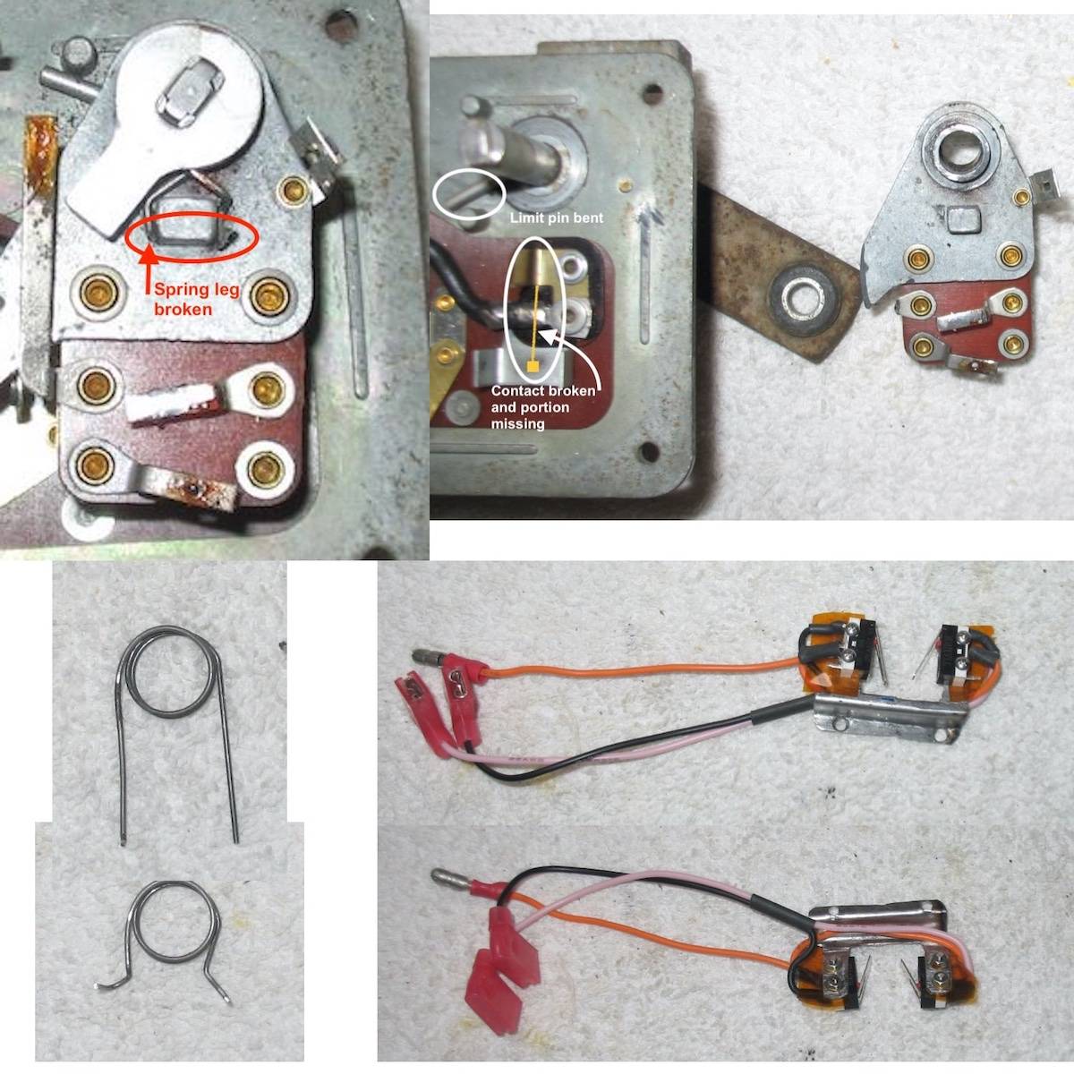
Riki, the levers probably could be bent a little and did give that some thought. Without on car testing decided to leave them as is for now. The switch actuates about mid lever travel but once it clicks there is not a lot of movement left before the lever hits the switch body. Will most likely wind up sending switch down so you can try your modified relays and check over the microswitch work.

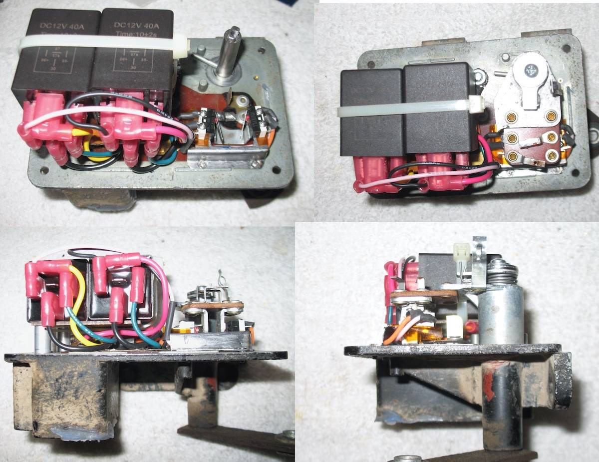
As mentioned before, because of the pivot side spring and contact issues this was going to be a throw away switch. It was completely gutted in the first attempt to find space to mount the relays. Originally was going to mount them vertically like the version with the board but after deciding a raised plate and different positioning would work, the full gut was not needed on the switch I used for the relay project.

Microswitches were then mentioned in regards to dirty pivot contacts and this switch became a perfect candidate for the project since it had no contact to start with. Tried to figure out something that would not require any mods at all to a good working switch pivot setup and this was the result. After seeing it maybe you can find a better or easier mounting method or another actuating location that does not require much caution or protection in making sure the wiring can not be damaged by the cover. If it was to be offered DIY, a best case would be some kind of bracket figured out and made using the same process Kev did with the bracket he made for the choke switch on his 37.

Since you actually drive your car maybe you will even be able to test the switch when you get tired of some of your other projects.

Posted on: 2023/5/17 9:49
Howard
 Top  Print   


Re: DIY Torsion level control switch conversion
#45
Home away from home
Home away from home

R H
See User information
Send Er down h.

I will test it.

If you want. Keep your relays.

I'll put the ones I have in.

Label the wires...

I'll check the time it takes. And adjust as necessary.. With the trimmers.

Or. Is 10 seconds about right with shorter throw.

Posted on: 2023/5/17 22:55
Riki
 Top  Print   


Re: DIY Torsion level control switch conversion
#46
Home away from home
Home away from home

R H
See User information
Later today. Time test.

Attach file:


jpg  20230603_050006_HDR.jpg (199.61 KB)
4498_647b34c7982c2.jpg 1920X1440 px

Posted on: 2023/6/3 7:41
Riki
 Top  Print   


Re: DIY Torsion level control switch conversion
#47
Home away from home
Home away from home

R H
See User information
Video.

6 second delay.

The levers on the micro switches might have to be bent .
All depends on linkage on car.

But all checks out.. Hh did a great r and d.


https://youtu.be/FsZ8p44KuMc

Posted on: 2023/6/3 15:28
Riki
 Top  Print   


Re: DIY Torsion level control switch conversion
#48
Home away from home
Home away from home

Packard Don
See User information
Looks great. Do you want to sell me one when you're done?

Posted on: 2023/6/3 16:09
 Top  Print   


Re: DIY Torsion level control switch conversion
#49
Home away from home
Home away from home

acolds
See User information
I also may be interested in one for spare

Posted on: 2023/6/3 18:12
C:\Users\veron\Desktop\New folder\1956 Packard Caribbean\753.jpg
 Top  Print   


Re: DIY Torsion level control switch conversion
#50
Home away from home
Home away from home

R H
See User information
Don.

Hh56 put that switch together.
I have not tried it.

The big pita is the bracket for micro switches

Hh was thinking 3d printing it if it can be made durable.

Relays are not big deal. Except for time. Its the most cost effective.. Way to get factory delay

22 dollars for relays .. Trimmers few bucks.
And micro switches few bucks.

It raises and lowers the car. Just have a glitch .. Which will be talked about later.

No big deal..

Posted on: 2023/6/4 4:52
Riki
 Top  Print   


« 1 2 3 4 (5) 6 7 »


Search
Recent Photos
Photo of the Day
Recent Registry
Website Comments or Questions?? Click Here Copyright 2006-2024, PackardInfo.com All Rights Reserved