|
Re: 1937 Voltage Current Regulator Voltage Draw
|
||||
|---|---|---|---|---|
|
Forum Ambassador

|
If the regulator is working and wired properly, when the engine is off there is a cut out contact in the regulator that opens totally disconnecting the battery from the regulator and charging system. Unless it is a faulty regulator there should be no way the battery is discharging back thru it.
If you have an AutoLite system there is an older and excellent training manual in the archive that details the function and how each part in the regulator and charging circuit operates. If your car has a third brush generator it even briefly touches on how those work. Delco works similarly but details are different. Here is a generic diagram showing the basic postwar charging circuit and how the cut out contact isolates the battery when the generator is not charging. As mentioned, AutoLite and Delco differed in some of the details but the basic operation is the same for both. Attach file:  Charging Circuit.JPG (72.90 KB) Charging Circuit.JPG (72.90 KB)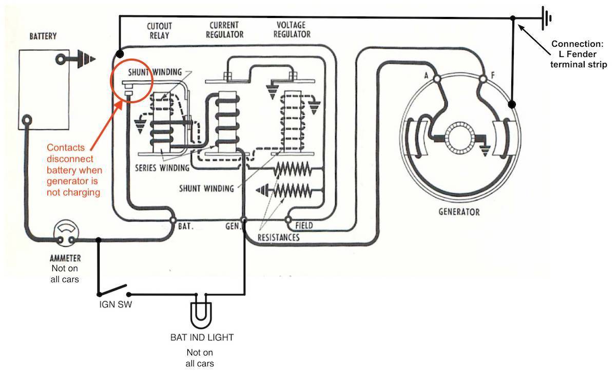
Posted on: 2022/9/4 16:44
|
|||
|
Howard
|
||||
|
||||
|
Re: 1937 Voltage Current Regulator Voltage Draw
|
||||
|---|---|---|---|---|
|
Home away from home
|
Thanks, that is what I thought should happen. I'll have to go into this one and see why the solenoid is closing and remaining closed when there is no current coming from the generator. I'll also get with the company that sold me my regulator and see what they have to say.
Thanks, again.
Posted on: 2022/9/4 16:52
|
|||
|
Roger Howe
Whitewright, TX 1937 120C Touring Sedan |
||||
|
||||
|
Re: 1937 Voltage Current Regulator Voltage Draw
|
||||
|---|---|---|---|---|
|
Home away from home

|
1/2 amp is way too high. I also believe your cutout relay is not working properly. If it keeps continuity, it powers the generator to make it like a motor, which just wastes electricity.
If you know what a diode is, a cutout relay does the same function. It's a combination volt and amp powered relay, when the voltage of the generator is high enough it connects, and the current then flowing thru it helps it connect more, so the disconnect voltage is some amount lower than the connect voltage, to reduce wear.
Posted on: 2022/9/4 18:13
|
|||
|
'55 400. Needs aesthetic parts put back on, and electrical system sorted.
'55 Clipper Deluxe. Engine is stuck-ish. |
||||
|
||||
|
Re: 1937 Voltage Current Regulator Voltage Draw
|
||||
|---|---|---|---|---|
|
Home away from home
|
Thank you. I now see the manner in which this type of regulator should work. However, the only replacement regulator I could obtain was one with only two solenoids and when I have it wired as I thought it should be, one solenoid closes thus causing the current draw. Does anyone have a wiring diagram for this Auto-Lite 6 volt two solenoid voltage regulator that would show me which post goes where; battery, generator, third brush?
Again, I appreciate any information that you might be able to provide.
Posted on: 2022/9/5 10:56
|
|||
|
Roger Howe
Whitewright, TX 1937 120C Touring Sedan |
||||
|
||||
|
Re: 1937 Voltage Current Regulator Voltage Draw
|
||||
|---|---|---|---|---|
|
Home away from home

|
Just an FYI that they are relays, not solenoids. They’re two different things.
Posted on: 2022/9/5 11:25
|
|||
|
||||
|
Re: 1937 Voltage Current Regulator Voltage Draw
|
||||
|---|---|---|---|---|
|
Forum Ambassador
|
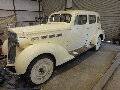
These are bits from the 37 120 factory wiring diagram which you can download from the literature archive or is in the 37 shop manual. If the 2 coil regulator which appears to be the Autolite version is similar to your replacement the diagram might work with what you have. There are two drawings showing Autolite and Delco regulators with slightly different placement of wire numbers to the generator.
Attach file: 2 coil reg.jpg (106.41 KB) 37 - 120.jpg (176.11 KB) 37 - 120.jpg (176.11 KB)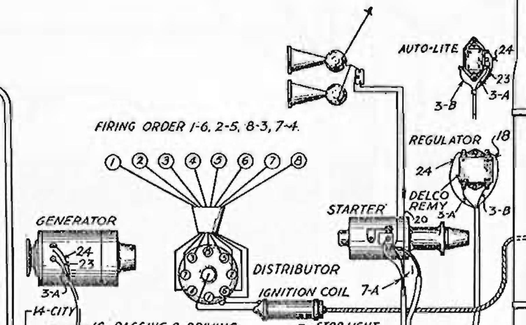
Posted on: 2022/9/5 11:26
|
|||
|
Howard
|
||||
|
||||
|
Re: 1937 Voltage Current Regulator Voltage Draw
|
||||
|---|---|---|---|---|
|
Home away from home
|
Thanks. Yes, I do know they are relays and not solenoids and I cannot tell you why I named them as such. I went back into the archives and looked at the service manual. Their illustration of the connection of the regulator is exactly how I had it connected, thus causing the power draw. Well, at least, I think that was the correct connection. It looks like from the illustration that pole B attaches to the battery and then that routes back through ground to the positive side of the battery, thus causing the relay to close. Do you know if the highly insulated relay coil is supposed to be the pole labeled B, from the battery, or pole F, the field input from the generator? From what I have been told, this is the input that allows the relay to close thus allowing the regulator to do its job.
Thanks again for your help.
Posted on: 2022/9/5 12:58
|
|||
|
Roger Howe
Whitewright, TX 1937 120C Touring Sedan |
||||
|
||||
|
Re: 1937 Voltage Current Regulator Voltage Draw
|
||||
|---|---|---|---|---|
|
Forum Ambassador
|
Wire 3B is the BAT connection and is coming from the ammeter. 3A is the armature wire from the generator and 24 is the field wire. 23 is a ground reference wire so the regulator and generator are at the same ground potential and no poor connections between sheet metal or metal to frame connections would affect the regulation..
One question is did you polarize the generator when you installed the new regulator. That is usually a necessary step to get all the charging components attuned to one another and to orient, reinforce and ensure the residual magnetism in the field shoes in the generator is at the proper magnetic polarity depending on how the battery is connected. Polarizing is done by using a short length of fairly heavy jumper wire to momentarily connect the BAT and ARM terminals on the regulator so a surge of current is fed into the generator. The connection is only held for a second or two and there will be a spark when the connection is made. It is mentioned on page 60 in the 37-38 service manual as well as a comment that the cut out relay contacts can be damaged if polarity is reversed or if regulator is disconnected improperly. The way a typical 2 brush generator/regulator works is when the generator starts spinning, the residual magnetism in the generator field shoes is just enough for the generator to start producing a small voltage and current -- enough to energize the shunt winding in the cut out relay coil and provide enough magnetism to pull in the relay. As soon as the relay pulls in the contacts close which allows full battery voltage to go back into the generator. In a two brush generator the field is also powered from the ARM terminal and the battery will fully power up the field coils. If the generator is one of the third brush variety that brush and how it is adjusted supply the field coil power instead of the battery and the brush will pick up enough current to power the coils. The brush generally serves as a limiting method but has disadvantages in regulation and generators have limited output at higher speeds so the two brush and 3 relay regulator evolved. The overall charging control and cut out relay will still be similar to the two brush type. Field coils at strength allows the generator to produce increased voltage and current. Once the output voltage and current are strong enough the series winding in the cut out coil strengthens the relay magnet and contact connection and also start working on the other coil(s) in the regulator which causes their contacts to open and close. That action connects either a solid ground or a resistance connected to ground in or out of the field wire. With a voltage on one side of the field coil and the ground or resistance on the other it strengthens or lessens the field to keep the generator voltage and current regulated to the set specification. Set generator voltage specification is usually about 1 volt above normal battery voltage so because it is stronger, that voltage is fed back into the battery and generator is charging. As long as the overall load is within the generator and regulator capabilities and settings the ammeter needle will stay on the charge side. When the engine shuts off, no more voltage and current coming from the generator allows the spring on the cut out relay contact to pull it open and break the connection to the battery so there should be no discharge back thru the generator or regulator.
Posted on: 2022/9/5 14:12
|
|||
|
Howard
|
||||
|
||||
|
Re: 1937 Voltage Current Regulator Voltage Draw
|
||||
|---|---|---|---|---|
|
Home away from home
|
Thank you and yes, I did see that paragraph on page 60 under "Important", however, it did not make much sense to me. Your explanation of what is supposed to happen makes that now more clear. I will have to wait until I return from my travels to correctly polarize the generator for I do not have the time now to reinstall my wiring harness and get everything set up. This will be on the top of my list when I return.
I have learned so much from all of you and you have my thanks.
Posted on: 2022/9/5 15:20
|
|||
|
Roger Howe
Whitewright, TX 1937 120C Touring Sedan |
||||
|
||||


.jpg")


