|
Re: One Wire 6 volt positive ground alternator
|
||||
|---|---|---|---|---|
|
Home away from home
|
Hello 1outta14chevys;
It sounds like you are exploring the possibility of replacing your generator and voltage regulator with an alternator. I agree with Phils38cpe in that you could use a Delco 10SI type alternator, or a 'generator look alike' alternator. Both of these units are available in 6 or 12 volt outputs, with either negative or positive ground. All of these 'one-wire' alternators would be connected to the existing wiring by a direct connection to the 'BATTERY' terminal of the voltage regulator. It's that easy! In my case I replaced the AutoLite generator on my '48 Deluxe Eight with a Power Master one wire alternator that looks like an old school generator. That would be a Power Master, PowerGen model 82056, which is a 6 volt positive ground 75 ampere unit. It is marketed to replace a Delco long case generator, but fits the '48 AutoLite application just fine. I did need to turn a spacer to accommodate the original Packard tension adjustment strap. I suspect if I have applied enough force I could have bent the strap to fit, but I'm not about to do that. These units are available with narrow or wide drive pulleys to accommodate neither drive belt configuration . . . mine is a 5/8 - 3/4 inch belt. I purchased the alternator from Quality Power in Yucaipa, CA. I did modify the unit by adding a dummy field pole, and also added an AutoLite generator tag and one of those condenser warning paper labels. Now for more details on the wiring, as I stated the unit could be connected directly to the 'BATTERY' terminal of the regulator, but my concern was connecting a unit with essentially twice the current capacity to the car's wiring. I did not know, and still don't, the failure mode of an ammeter presented with twice the design maximum current. I built a harness with two conductors; one was routed to the aforementioned regulator 'BATTERY' terminal, and the other was attached to the battery side of the starter solenoid. Now about ? the maximum recharge current is presented to the original Packard ammeter during charging, and all of the current is presented to the ammeter during discharging. Since the 'load side' of the circuit has not changed the maximum amount of battery discharge, for the lights, radio, and horn, should be identical to the original value, and the ammeter has demonstrated for 67 years that it's up to the job. If you insulate the field and armature wires removed from the original generator the other end of those could be left attached to the voltage regulator. The wire attached to the dummy field pole is quite short and connected to the alternator only . . . it isn't attached to anything else. I used fusible link wire to protect the alternator harness and used 'cotton' covered wire throughout to maintain the illusion of 'correctness'. I wired a voltmeter to a cigarette lighter plug and monitored the performance to the new alternator. My impression is that the unit begins charging just off low idle, and runs at 7.45 volts pretty much all of the time. It does drop to battery voltage at dead low idle. During start-up the engine rpm's are high enough to establish charging. I'm satisfied that the charging system has been upgraded to almost modern standards, and by using an alternator look alike alternator the vehicle visual authenticity has not been clobbered quite as much if I had used a Delco 10SI alternator. I'm happy with the upgrade. dp
Posted on: 2015/8/25 15:21
|
|||
|
||||
|
Re: '48 Head Light Switch & Circuit Breaker
|
||||
|---|---|---|---|---|
|
Home away from home
|
The '48 circuit breaker is replaceable without removing the switch. Modern breakers appear to have the same geometry as the historic examples, so availability is not an issue. The breaker does not have a built-in mounting bracket so you might have to shop around. I use DelCity.Com for my automotive electrical materials (switches, wire, shrink tubing, connectors). I did remove the front seat cushion to make it a bit easier to get comfortable on what I was expecting to be a long job . . . it wasn't . . . long that is, but I could never find a good place for the 'string light'.
The modern unit operates at least 30 degrees cooler than the original item (135 F v 165 F), and the modern unit data was recorded at a higher outside air temperature than the original which matters with circuit breakers. Only the wire connections with 'bullet connectors' need to be removed so remember with color wire goes where. So far so good. I'll re-post if the diagnosis was wrong, or the modern unit isn't up to the job. I measured about 16-20 amps passing thru the breaker (2 headlights, 2 tail lights, 1 license plate bulb) and installed a 30 A modern unit. If the Packard original unit was marked that ink left the station long ago. I've also read that circuit breakers have a finite life if they are asked to open and close. One source indicated about 50 cycles before the arcing at the contacts renders the breaker useless. dp
Posted on: 2014/6/19 19:07
|
|||
|
||||
|
Re: Cavalier Electrical Accessory
|
||||
|---|---|---|---|---|
|
Home away from home
|
I'm familiar with those units. The folks that build them suggest not to use them on devices with high initial current flow such as incandescent lighting. They do have an excellent track record powering the type of devices you mentioned.
The circuit I'm working on would be on the point side of the tachometer where the switching frequency is in the order of 100 Hz. In either the tach application or with steady state signals like the stop, turn, or tail lights the load on the 6 volt side will be something like 0.02 A, which should not jeopardize the wire harnesses or switches of the car. The load on the 12 volt side will be totally dependent on the equipment installed, however I can limit the current through my circuit to approximately 0.3 A by driving a relay and allow that set of points carry the full 12 volt load. I've got 6 volt relays up to and including an 80 A rating. The voltage rating of the relay in this case refers to the voltage required to activate the switching feature of the relay. The main set of contacts have sufficient dielectric characteristics to withstand many times the anticipated 12 volts. dp
Posted on: 2014/3/31 15:10
|
|||
|
||||
|
Re: Cavalier Electrical Accessory
|
||||
|---|---|---|---|---|
|
Home away from home
|
No current plans to go crazy with the audio capability.
I do reserve the right to re-charge a phone or tablet and operate a GPS if need be. I'm also working on an integrated circuit that will allow a car buff to install a modern tachometer, which would normally constructed to function with 12V negative ground power and ignition signal, into one of our 6 volt positive ground cars. There are some low RPM, 270 degree sweep units that would be quite beneficial in either the car or shop. The same circuit design should work on installation of additional LED stop, turn, and tail lights, if that be needed. I have some experience driving cars that are significantly sub-sonic with respect to the rest of the traffic. The additional rear illumination appears to awake the over-taking driver at a respectable distance. I have one installation equipped with 4 way flashing capability which I believe is capable of bring the approaching driver out of a cell-phone induced coma even during the day-light hours. Unless your willing to purchase all of the LEDs individually and spec-out the correct resistor for each, most of the pre-packaged assemblies are for 12 volt. I have had success with the Radio Shack individual 12 volt LEDs (available in red, amber, & green). They light-up just fine on 6 volts, I guess that would be 6.5 - 7.5 volts. I've got one hooked-up to the over drive circuit on the '54 Cavalier, much like the feature on the '48 Deluxe Eight. dp
Posted on: 2014/3/31 12:09
|
|||
|
||||
|
Cavalier Electrical Accessory
|
||||
|---|---|---|---|---|
|
Home away from home
|
I'd like to share the details of an electrical accessory I built for my '54 Cavalier. The motivation was to install a modern radio well hidden from view, but since those are 12 volt negative ground units something at bit more complex than throwing it under the seat was in order.
The photo in the upper left is a mock-up of the system during construction. When I bought the car it had 1 inch rough-cut oak seat riser blocks. This riser is comprised of two ? inch oak pieces, which afforded me the opportunity to have a 'shelf' to rest the outer edge of the assembly. You can see the counter sunk bolts that anchor the unit to the riser. The riser block on the right side of the seat does not feature a shelf in that the under seat heater core pretty much takes-up all of the room. Given the 'sag' in the seat cushion the extra ? inch is not noticeable. The upper right photo, again taken during construction is looking down on the unit. The Secret Audio radio is visible as are the auxiliary relays, fuse block, and sundry electrical components. The yellow item in the upper left corner of this picture is a switchable magnet. There are two of these items along the in-board edge. Each magnet is rated at 95 pounds and allowed me to mount the entire unit without having to drill any holes in the floor pan. A ? turn of the knob activates the magnet, and with two of these little devils and the bolts at the other end the entire system is well secured into the car. The photo in the lower left depicts the finished product as installed under the front seat. I have subsequently abandoned the idea of supporting the cable bundle from the seat adjustment rod . . . just in case someone re-adjusts the seat! The radio is controlled by either a dash panel display or an RF remote fob. I use the remote most of the time. The dash panel display current rests on the transmission hump while 'under-way' and hidden from view when it matters. The final photo is the view you would have if you happened to fall-down face first into the driver's foot well. I went a bit overboard on the number of switches, but I'll probably not out-grow the electrical capability in the future. The switch labeled "Master Power' activates the entire unit via an 80 Amp relay. The switch labeled "Fuel Pump" activates the 6 volt positive ground pump that is used to refill the carb after the car sits un-used for a few weeks. The two voltages do not share anything in common except the aluminum panel to mount the switches. Also visible are the cooling fins of the radio amplifier, and a ubiquitous 12V power plug. Having the 'Master Power' and 'Fuel Pump' switches at the opposing ends make them quite easily activated from the driving position. The pump switch is a SPST momentary, while all other positions are filled with SPST continuous switches. All of the power cables are routed along the floor and over the left rear wheel 'tub' into the trunk. Currently a 12 volt automotive battery is placed in the truck without the benefit recharging while underway. My calculations suggest that I could power the radio continuously for over four days. The longer range plan is to provide on-board recharging and use two 6 volt batteries in series versus one 12 volt battery. The 6 volt battery modification is likely to happen before, make that well before the voltage conversion unit is installed. At the end of the day my car is equipped with a modern radio that I can plug an I-Pod or I-Pad into, and the OEM radio and remote antenna remain in suspended animation safe from use. I remember in the day mechanical vibrators had a finite life span as well the 'valves'. Attach file:  (127.47 KB) (127.47 KB)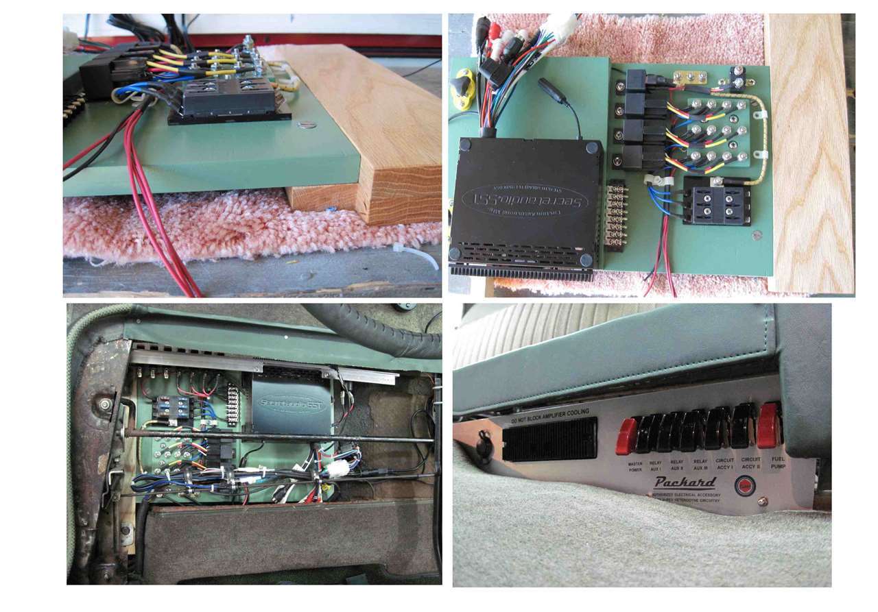
Posted on: 2014/3/30 23:24
|
|||
|
||||
|
Re: '48 Head Light Switch & Circuit Breaker
|
||||
|---|---|---|---|---|
|
Home away from home
|
Thank you HH56;
If I understand your explanation correctly all of the switches are mounted to a sub-structure that itself is mounted to the chrome cover with two nuts that have a slotted screw driver slot. Once the switches and sub-structure are released from the chrome cover each switch may be removed by the single attachment nut. I presume that the dash is between what I'm calling the sub-structure and the chrome cover/trim. I understand your comment about the heater/defroster & air control unit. For such a large car, why is it always a challenge to work under the dash? To date I have not found a transient path to ground, but I understand that my tests have been static, that is, the car not moving. I will inspect all wiring in the trunk . . period. All of the harnesses have been replaced 14 years ago. Thanks again . . . oh one more question. Do you think the head light circuit breaker could be swapped 'in situ' thus limiting the disassembly? It would appear that two hex nuts hold the circuit breaker to the Micarta back panel of the switch. dp
Posted on: 2014/3/30 0:14
|
|||
|
||||
|
'48 Head Light Switch & Circuit Breaker
|
||||
|---|---|---|---|---|
|
Home away from home
|
I have a question about my "brand new '48 Deluxe Eight". The headlights cycle on and off much like the circuit breaker is opening and closing. I have measured the total current in both high beam and low beam operation, the current flow is in the order of 20 amperes total with the low beam having a slightly lower current. That would be well within the nominal range. There does not appear to be any transients in the reading but since the test was rather short the lights remained on throughout. When I'm out on the road the ammeter occasionally has the heebie-jeebies when the lights are ON and rock steady with them OFF. I suspect the poor regulator is trying (but failing) to keep-up with the potential of an ON/OFF 20 amp transient load. The question I have is how does one remove the chrome outer switch cover to gain access to the nut that secures the switch/circuit breaker assembly to the dash. I'd rather ask before I break something. I would like to remove the assembly and run a few 'under load' bench tests with the current circuit breaker and with a modern unit as a comparison.
To date I've checked the beam selector 'toe-switch',and inspected for chaffing . . . all is well. I've added temporary fuses in the low beam circuits (one for each), the fuses are being used as 'tattletales', but they too are in good shape.
Posted on: 2014/3/29 22:44
|
|||
|
||||


