 (127.47 KB)
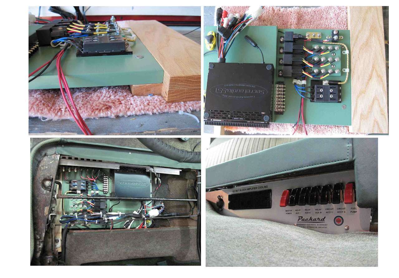
|
Re: Cavalier Electrical Accessory
|
||||
|---|---|---|---|---|
|
Forum Ambassador

|
Nicely done. That looks like it could run a serious sound setup.
I parked next to a guy at the shopping center that had filled the back of a PT Cruiser with speakers and sound equipment. Whatever kept that tin car together and firmly on the ground with those things blasting away, I couldn't say. At least your Packard has enough metal that it will have a chance of staying grounded and in one piece if you go that route.
Posted on: 2014/3/31 9:15
|
|||
|
Howard
|
||||
|
||||
|
Re: Cavalier Electrical Accessory
|
||||
|---|---|---|---|---|
|
Home away from home
|
No current plans to go crazy with the audio capability.
I do reserve the right to re-charge a phone or tablet and operate a GPS if need be. I'm also working on an integrated circuit that will allow a car buff to install a modern tachometer, which would normally constructed to function with 12V negative ground power and ignition signal, into one of our 6 volt positive ground cars. There are some low RPM, 270 degree sweep units that would be quite beneficial in either the car or shop. The same circuit design should work on installation of additional LED stop, turn, and tail lights, if that be needed. I have some experience driving cars that are significantly sub-sonic with respect to the rest of the traffic. The additional rear illumination appears to awake the over-taking driver at a respectable distance. I have one installation equipped with 4 way flashing capability which I believe is capable of bring the approaching driver out of a cell-phone induced coma even during the day-light hours. Unless your willing to purchase all of the LEDs individually and spec-out the correct resistor for each, most of the pre-packaged assemblies are for 12 volt. I have had success with the Radio Shack individual 12 volt LEDs (available in red, amber, & green). They light-up just fine on 6 volts, I guess that would be 6.5 - 7.5 volts. I've got one hooked-up to the over drive circuit on the '54 Cavalier, much like the feature on the '48 Deluxe Eight. dp
Posted on: 2014/3/31 12:09
|
|||
|
||||
|
Re: Cavalier Electrical Accessory
|
||||
|---|---|---|---|---|
|
Home away from home
|
I purchased one of those 6V pos grnd to 12V neg grnd convertors from Ebay and it runs a modern am/fm radio very nicely in my 38, also I hooked up another unit for cell phone charging/gps usage. The convertors supply about 2.5-3 amps.
Posted on: 2014/3/31 13:01
|
|||
|
1938 1601 Club Coupe
|
||||
|
||||
|
Re: Cavalier Electrical Accessory
|
||||
|---|---|---|---|---|
|
Home away from home
|
I'm familiar with those units. The folks that build them suggest not to use them on devices with high initial current flow such as incandescent lighting. They do have an excellent track record powering the type of devices you mentioned.
The circuit I'm working on would be on the point side of the tachometer where the switching frequency is in the order of 100 Hz. In either the tach application or with steady state signals like the stop, turn, or tail lights the load on the 6 volt side will be something like 0.02 A, which should not jeopardize the wire harnesses or switches of the car. The load on the 12 volt side will be totally dependent on the equipment installed, however I can limit the current through my circuit to approximately 0.3 A by driving a relay and allow that set of points carry the full 12 volt load. I've got 6 volt relays up to and including an 80 A rating. The voltage rating of the relay in this case refers to the voltage required to activate the switching feature of the relay. The main set of contacts have sufficient dielectric characteristics to withstand many times the anticipated 12 volts. dp
Posted on: 2014/3/31 15:10
|
|||
|
||||


