|
Re: Stewart's 1955 Packard 400
|
||||
|---|---|---|---|---|
|
Home away from home

|
Finally a break in the cold.
I went out today and tested the T/L as previously suggested. I hooked the battery up as shown in the graphic that Howard posted and nothing happened when I moved the control switch. I tried it with both positive and negative ground and no movement or a sound. When I tested both terminal on the motor and both solinoids it worked fine but the control switch did nothing. Its probably for the better. As Howard explained when Packard service centers installed a 56 switch on a 55 unit it was rewired to permit positive ground so if I get a normal 56 switch I can continue to plan on negative ground through out. Also, when I replaced the solinoids I got the model that was already rubber coated as seen in other photos I have posted. That did not work out so well. A single solinoid is about 3/16 larger then the old one. Both mounted to plate are 3/8 larger and would not fit when mounted to the compensator unit. I had to trim off some of the thick coating to mount it correctly. I will re-coat with the brush on stuff once I know everything is working. Attach file:  (95.02 KB) (95.02 KB)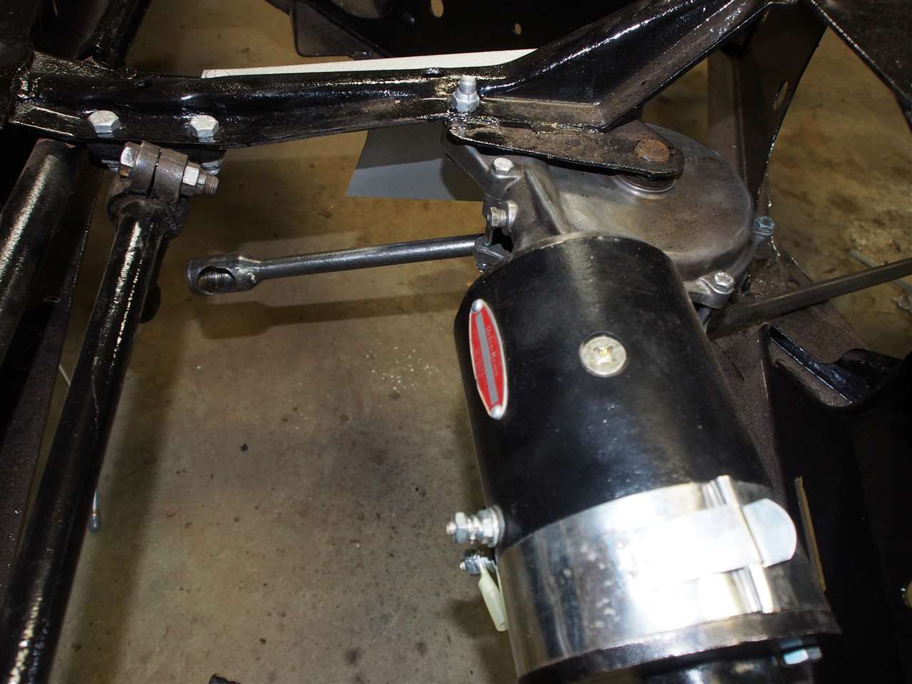 (109.04 KB) (109.04 KB)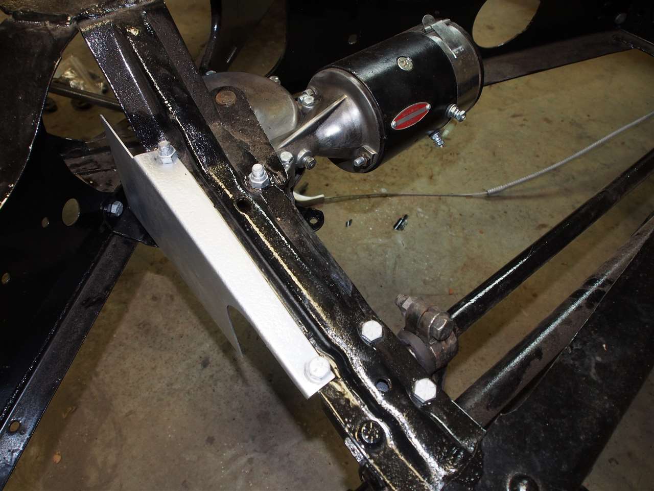 (100.54 KB) (100.54 KB) (112.73 KB) (112.73 KB)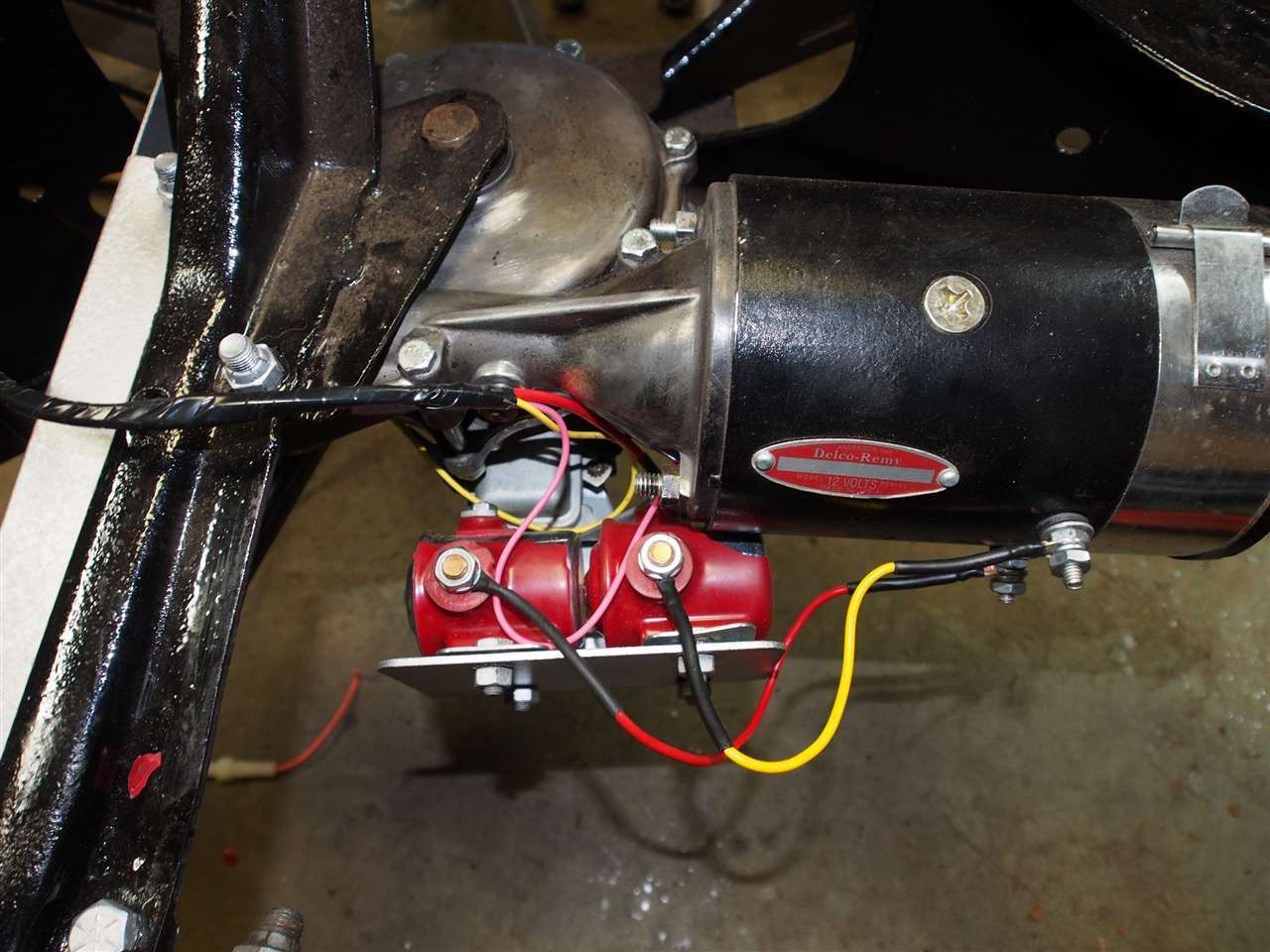
Posted on: 2016/1/24 18:08
|
|||
|
Stewart Ballard
|
||||
|
||||
|
Re: Stewart's 1955 Packard 400
|
||||
|---|---|---|---|---|
|
Home away from home
|
Man, that T/L is looking sweet!!!!!!

Posted on: 2016/1/24 18:15
|
|||
|
[url=https://packardinfo.com/xoops/html/modules/
|
||||
|
||||
|
Re: Stewart's 1955 Packard 400
|
||||
|---|---|---|---|---|
|
Forum Ambassador

|
I'm not familiar with the red solenoids. Are they the correct type? Ordinary starter solenoids you get from the parts store typically need a voltage to energize because the coil is grounded. The Packard solenoids have the coil connected to voltage internally and need a ground to energize. Also, because of the coil being connected to voltage internally the solenoids have to be positioned so the battery is on the correct large terminal. Both of those discrepancies have been problems for others in replacing solenoids.
On the control switch, if it is the original bimetal heater type it is not polarity sensitive. If the solid state retrofit then it may be and hopefully there will be something from the vendor or a sticker on the box cautioning the user. That polarity issue is a big question mark on those refits that I have never heard a solid yes or no answer to. Unless internally protected, if it is solid state a wrong hookup could have damaged the solid state components.
Posted on: 2016/1/24 18:25
|
|||
|
Howard
|
||||
|
||||
|
Re: Stewart's 1955 Packard 400
|
||||
|---|---|---|---|---|
|
Home away from home
|
I though you might like that Troy.
Howard I discussed the solenoids in post 346 (page 35 I think). It is just a rubber coated version of the model that was suggested in the parts x-ref page.
Posted on: 2016/1/24 18:41
|
|||
|
Stewart Ballard
|
||||
|
||||
|
Re: Stewart's 1955 Packard 400
|
||||
|---|---|---|---|---|
|
Forum Ambassador
|
I would verify both solenoid type and hookup by using a clip lead to momentarily ground the small terminal. If the motor kicks then at least you know the problem is before the solenoids. If no action then solenoid is wrong or power is applied to the wrong large terminal.
Posted on: 2016/1/24 18:46
|
|||
|
Howard
|
||||
|
||||
|
Re: Stewart's 1955 Packard 400
|
||||
|---|---|---|---|---|
|
Home away from home
|
Howard
I am not 100% sure what you mean by "the small terminal". Do you mean the small one on each solenoid (where the limit switch connects)? I tried that an nothing happened. I've gone over all the wiring multiple time and its all wired exactly as described in the wiring diagram. I also tried the testing diagram that you uploaded last week and still no results from the control box
Posted on: 2016/1/25 18:39
|
|||
|
Stewart Ballard
|
||||
|
||||
|
Re: Stewart's 1955 Packard 400
|
||||
|---|---|---|---|---|
|
Forum Ambassador
|
Yes, the small terminal is where limit switch connects. One thing I am wondering is the orientation of the solenoids. You can check with a volt meter.
If you measure 12v to ground at the long incoming buss bar from the fuse and connecting the two solenoids via the large terminals, assuming the control switch is not connected or at least not energized you should also have 12v to ground at the small terminals. If you do then the problem is before the solenoids -- either limit sw or control sw. If you have voltage at the buss bar but do not have 12v at the small terminals there are two possibilities. One is the solenoid is the wrong type and the coil is internally grounded. Those need a voltage to operate and won't work in the TL. The other is the solenoid is oriented or mounted backwards so the buss bar carrying incoming power is on the wrong or output side large terminals. If you look at the drawing, at the end of the red arrows the proper solenoids for the TL have the coil internally connected and powered by one of the large terminals. A ground on the small terminal will energize those type solenoids. If the solenoid is backward and power is on the output side terminal, the coil cannot get any power. There will be no reading of voltage at the small terminal and no way to energize the solenoid. Usually the type with internally connected coils will have a Battery label on or near one of the large terminals. Attach file: (97.90 KB)
Posted on: 2016/1/25 19:07
|
|||
|
Howard
|
||||
|
||||
|
Re: Stewart's 1955 Packard 400
|
||||
|---|---|---|---|---|
|
Home away from home
|
Your 12 volt electrical knowledge sure exceeds mine but I'll bet you already figured that out.
I had no idea there was an input and output specific side on these Solenoids. I looked up the specs and they made no mention of that nor is it marked on the solenoid itself. The Specs are below Description Intermittent Duty Solenoid Special applications Universal Insulated/Grounded Insulated NO/NC normally open Circuitry SPST Contacts copper Housing phenolic Voltage rating 12V Maximum current: make 750A Maximum current: break 100A Intermittent time 10 sec. On - 20 min. Off I will see what I can do tomorrow night.
Posted on: 2016/1/25 19:56
|
|||
|
Stewart Ballard
|
||||
|
||||
|
Re: Stewart's 1955 Packard 400
|
||||
|---|---|---|---|---|
|
Home away from home
|
Went out tonight to test everything with the multi-meter.
I printed out last nights instructions to take with me. First thing I did was test the control box. Since I already had it wired per Howard's instructions in post 370 it just made since. I powered the control box with a positive ground and tested the yellow lead on the limit switch to ground and then moved the control box arm. I got a reading of 1.5. I then tested the pink lead to the limit switch and also got a 1.5. I guess the switch is good after all. Oddly I only got the 1.5 reading when I pushed the lever toward the center of the frame. When I pulled the level toward the outside of the frame I got no reading at all. I just assumed it would work both ways since it goes up and down (but what do I know) Finally when I changed it to negative ground I got no reading at all. Now I know its a 56 switch that was modified for a 55 w/ positive ground. Then I tested the buss bar on the solenoids per last night instructions and got 12 amps. I got nothing at all at the short terminals or the longer terminals on top. I still do not know if the solenoids are right side up. Worse case scenario I have to buy two solenoids $75 each as Max's and another 56 control box so I can use the negative ground. I think that's $180 at Max's. Yepee!
Posted on: 2016/1/26 19:41
|
|||
|
Stewart Ballard
|
||||
|
||||


