|
Re: KPack's 1954 Panama
|
||||
|---|---|---|---|---|
|
Home away from home
|
Hi Kevin
Dorman makes those clips. You may however have to buy an assortment to get the one you need. DP
Posted on: 2024/9/10 11:06
|
|||
|
||||
|
Re: Rear axle help (54-55)
|
||||
|---|---|---|---|---|
|
Home away from home
|
HPH
That’s an excellent question! I have an idea/theory that would never be obvious if we are only looking at the cut-away drawings in the shop manual. First, other what part spins and what part is standing still, that design is similar to a modern front wheel spindle/hub design, which doesn’t use a sleeve. Second is the historic Brand X pinion bearing preload design that equally doesn’t use a sleeve. A common element between these two designs is a means to lock/safety the adjusting nut, which may otherwise be tightened to a torque that would be far too low to ensure non-loosening during operation. A modern front wheel bearing set is torqued to some low level intended to remove all looseness and apply some preload to the bearing set. Then the adjusting nut is ‘backed-off’ so many wrench flats and a cotter pin installed. The original VW beetle used a design that used a pinch bolt in lieu of a cotter pin. In the Brand X pinion there are two nuts separated with a tab washer. The first nut is used to adjust the bearing preload, and once that is achieved the second nut is used as a jam nut. The tab washer is ‘tabbed’ to hold both nuts relative to the shaft. I see the crush sleeve as a means to force the torque on the pinion nut high enough to be less susceptible to loosening. I still look at that design as driven by manufacturing simplicity. dp
Posted on: 2024/9/8 15:18
|
|||
|
||||
|
Re: Carburetor WCFB 4-Barrel
|
||||
|---|---|---|---|---|
|
Home away from home
|
I believe the design intent is for the cap to close before the transition onto the main circuit, and be full open at idle and engine shutdown. You might ask why not have it open at all times, the answer of which goes back to the air filter pressure drop, where venting to the airhorn is superior. Another draw-back of venting directly to atmosphere, as in the Carter WDO, is the possibility of debris entry and the possibility of blocking air bleed orifices. While I’ve never found rocks in the WDO air bleeds I sure have found gravel in a Zenith design that vents to atmosphere through a hole that is about 3/8 diameter. If the cap doesn’t close completely the carburetor would have two vent paths, however if the car is equipped with an oil bath air filter that is of lesser importance with respect to enrichment. The air flow into the cap will however be higher, and thus the possibility of debris entry. A second function of the cap is to vent the carburetor to atmosphere during shutdown, and thus provide an exit path for fuel vapor. The goal would be to have sufficient valve area to keep the internal pressure low enough to avoid percolation discharge from the main discharge nozzle (hot start problem). Over a period of a few months my WCFB always seems to have fuel residue around the cap, which I suspect validates that venting does occur as intended. The check and adjustment of the cap motion should be conducted with the dust cover gasket (pn 121-208) in-place.
dp
Posted on: 2024/9/8 12:12
|
|||
|
||||
|
Re: Carburetor WCFB 4-Barrel
|
||||
|---|---|---|---|---|
|
Home away from home
|
53 Cavalier
IMO no sealing, other than metal on metal, is required at that location. The Carter illustrated parts list does not show a seal or gasket sealing the cap to the cover. The WCFB being a ‘modern’ carburetor vents the float bowls to the air horn. This was done primarily to avoid the tendency of enriching when the air filter produces more pressure drop. Paper air filters were replacing the oil bath designs during this same time period, and the oil bath design rarely would produce excessive pressure drop . . . not so the paper filters. The following is contained in a Carter service manual: 23. To make the bowl vent cap adjustment, install the metering rod dust cover. Close the throttle valve tightly and the bowl vent cap should lift 1/16". Bend the actuating arm to obtain the correct lift. Artwork attached . . . Note no gasket or seal is shown. dp Attach file:  CarterWCFBVentCap.jpg (42.32 KB) CarterWCFBVentCap.jpg (42.32 KB)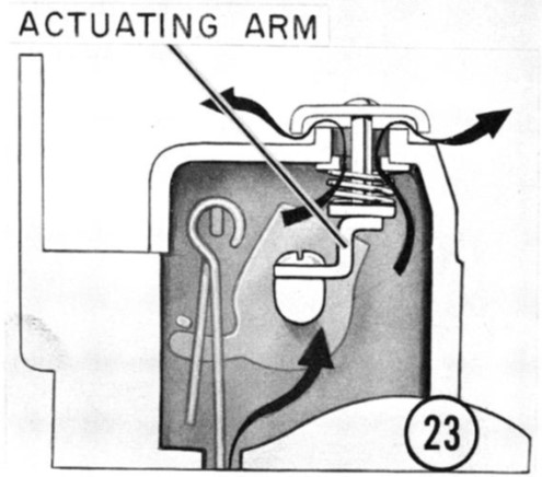
Posted on: 2024/9/8 11:21
|
|||
|
||||
|
Re: 1950 packard 288 engine just rebuilt now has water in the oil
|
||||
|---|---|---|---|---|
|
Home away from home
|
Slatewood
The good news is perhaps there may not be anything wrong with the engine. Unless you have installed a coolant recovery tank every time you top-off the coolant level you reset a process where the liquid will seek the same volume as the radiator/engine. You likely start with the prescribed volume cold/cool, but once the coolant warms the pressure rises, the cap opens and some liquid is expelled. Without a ‘catch-can’ once the liquid cools the cap vacuum feature opens and air is drawn into the system. I have been led to believe that as long as the liquid covers the ‘tubes’ the system has a sufficient level. I would top-off the level and warm the engine to full operating temperature, plus a little bit of idling in the garage. Let the engine completely cool (maybe the next morning), and determine the coolant level. Do not add coolant unless you can see the tube tops are dry. Repeat the process of using the car, idle a bit, allow a full cool-down, and recheck the coolant level. The difference between the two level checks is likely the amount of coolant the engine used/leaked. My bet the thermal expansion of the fluid has masked that true usage. Remember every time the coolant temperature hits a new high, some amount of fluid will be expelled. Insert my ‘war story’ of the big puddle of water under Brand X every time I used it! That is until I stopped over filling it. dp
Posted on: 2024/9/1 11:13
|
|||
|
||||
|
Re: Bucking Slightly at Cruising Speeds
|
||||
|---|---|---|---|---|
|
Home away from home
|
Joe I made a significant reduction in similar set of symptoms on my ’48 288 (WDO) by shimming the vacuum piston (aka vacumeter) spring. I left the metering rod adjustment (T109-113) alone and only shimmed the spring with an AN #4 screw flat washer 0.040“ thick, installed in the piston. Somewhere in the mountain of Carter/Packard technical advice I’ve read that spring should be replaced whenever the carb is open for service, however the kits I have bought recently did not include this spring. If that historic advice is well founded perhaps the vacumeter spring takes a set with use, and the mixture will tend to lean with age.
dp
Posted on: 2024/8/2 19:36
|
|||
|
||||
|
Re: Front Bumper Bolts, '56 Senior
|
||||
|---|---|---|---|---|
|
Home away from home
|
Pete ‘56
More than likely the bolt that has a Packard part number has a decorative head, while the ‘G’ part number is a general hardware item. The utility fasteners will not be visible when the bumper is viewed during a casual ‘walk around’, and can be found behind guards and attaching the brackets to the frame. I believe the ‘G’ designation also indicated to the dealer that the item could be procured locally. In group 50.050 there are plenty of ½ - 20 cad plated carriage bolts, which somewhat supports the assumption that the Packard part number would likely be the visible/decorative bumper bolt. If the intent was for the dealer to locally procure the utility items, then additional technical information (diameter/pitch/length) would be required, not so much for the Packard part number items. dp
Posted on: 2024/6/27 20:03
|
|||
|
||||
|
Re: Clipper registrations in '55 and '56
|
||||
|---|---|---|---|---|
|
Home away from home
|
Don, I understand and appreciate your preciseness to detail on this subject.
Don other than badging are there any identification plates that state ‘Clipper’ on your car (same question for R Anderson)? The web confirms that for ’56 only, the Clipper was classified as a stand-alone marque produced by the Studebaker-Packard Corporation, so I assumed some type of ID plate would contain the name Clipper, only because later ID tags for other short lived ‘brands’ identified the new brand name. The web also acknowledges a process of authorization of Clipper dealers by the S-P Corporation prior to the ’56 model year, and if there was no Packard dealers close at hand Studebaker dealers could join in and become Clipper dealers. My assumption is we likely had local businesses that were Packard-Clipper dealers, or Studebaker-Clipper dealers, but no Clipper alone dealers. I’ve also assumed that HH56’s comment about state’s bureaucracy is absolutely true, in that the 48 individual states would have to agree/approve that the ‘new brand’ met the automotive standards for that state, prior to the titling/registration process. Perhaps there were gaps in the state submittal/approval process for the ’56 Clipper, but the car would otherwise be acceptable if registered as a Packard. All of this surely predates the ’58 ‘Monroney sticker’ legislation, and 17 character VINs. Sounds a lot like the 4 GM companion cars in the late ‘20s R Anderson’s comment about last couple of years confusion seems to explain the situation quite well. At the local car shows I have a hard enough time explaining my car is a Packard, but imagine trying to explain a Clipper. I won’t mind having a ’56 Clipper as long as it was a standard transmission, non-power brakes, and non-torsion bar suspension . . . assuming there was one of those produced as long as we are going rare let’s go all the way. dp
Posted on: 2024/6/21 18:41
|
|||
|
||||
|
Re: Clipper registrations in '55 and '56
|
||||
|---|---|---|---|---|
|
Home away from home
|
My 2 cents is the local DMV would look at the cowl/identification plate and whatever manufacture is identified that would be what goes on the title and registration. I’ve surfed a bit and found all kinds of ID plates, however when I include ‘Clipper’ into the search the only returns are for boats/ships.
dp
Posted on: 2024/6/21 16:25
|
|||
|
||||
|
Re: Rear axle help (54-55)
|
||||
|---|---|---|---|---|
|
Home away from home
|
HPH
Pinion bearing adjustment is somewhat similar to adjusting the clearance of the outboard axle bearings, except in the case of the pinion bearings the clearance is considered negative, meaning the bearings are tight enough to produce a rotational drag. Some manufactures used a shimming procedure that was somewhat iterative. I don’t know of any designs that had a threaded adjustment for the pinion bearing adjustment, but given the number of designs there may be at least one that featured an adjustable feature, but alas not the Packard design. Fast forward to a simpler design of setting pinion bearing preload that does not require a distance measurement, or shimming, and can be done once and once only. This simpler design places a spacer between the bearings. This spacer is a piece of tubing (pinion gear passes through the center) that starts life longer than needed. A long spacer results in loose bearing that would have much less than the required drag torque. One more special feature of this design is the spacer tubing has a bead rolled in it. The bead is proud on the outer diameter. Most shop manuals suggest this bearing spacer is a ‘use once’ item. As the pinion flange nut is tightened the inner races of both bearings and the spacer become in intimate contact, but may not yet be the correct total length. Addition tightening of the flange nut begins to collapse the tubular spacer and the length is approaching the correct length. The bead in the tubing is the location where all of the plastic deformation is occurring (that’s why the bead is there in the first place) . . . the spacer is getting shorter. You continue this process until the required drag torque is correct. By using a collapsable spacer the pinion bearing drag is an assembly process that is not iterative. One of my non-Packard shop manuals suggests a torque of 350 ft-lbs may be required to collapse the spacer. The forums advise on pinion seal replacement stress the idea that getting the pinion nut back to the same position with respect to the pinion shaft is a recognition that the collapsable spacer should be returned to the same load / dimension . . . not tighter, or looser. Ultimately, we’re trying to get back to the same bearing preload. Since you have a bare case you will be determining the correct spacer length by measuring the rotational drag of the bearings and seal. By the way, the bearing drag adjustment is a completely different process from the pinion depth shimming. dp
Posted on: 2024/6/16 22:00
|
|||
|
||||


