|
Re: Polarizing generator
|
||||
|---|---|---|---|---|
|
Forum Ambassador

|
Quote:
Agreed, repolarizing is usually not necessary if it was only a wire disconnection. If you do try repolarizing it will not hurt anything but be sure the jumper is used to briefly short between ARM (or GEN) to BAT. Do not connect anything to the FIELD terminal except the wire going to the generator.. 
Posted on: 7/9 8:54
|
|||
|
Howard
|
||||
|
||||
|
Re: Stewart's 1955 Packard 400
|
||||
|---|---|---|---|---|
|
Forum Ambassador
|
Bummer! I was hoping you had found the right type paint and would share. All paints that I have tried have the same issue -- dull when viewed thru the plastic. I have tried different brand spray paints and plastic model brush on stuff but all had the same results. I know there must be something that works because there have been photos of "restored" emblems where the red, silver and gold do seem to shine thru. On one of the other make car forums someone said a special acrylic paint would work but then no details were given as to a brand, what was special about it or what prep was needed etc.
Sure would be nice to know what EmblemMagic does. IIRC, someone on the forum said they had quit operation but their website is still active so I don't know the situation. Their about us section says he made his first plastic emblem for a Chrysler trunk in 89 so there must be some kind of process that is available.
Posted on: 7/7 18:39
|
|||
|
Howard
|
||||
|
||||
|
Re: Ultramatic gearbox problem slipping direct drive clutch
|
||||
|---|---|---|---|---|
|
Forum Ambassador
|
Quote:
PS: In the Packard Service Technician Training Book on page 24 it says about Shifting from Low Range to High Range and from High Range to Low. This shift between gears is something Packard worked on several times during the life of the original Ultramatic because as transmissions from other mfgs became available they found themselves somewhat at a competitive disadvantage. The shift is possible in theory as Packard described it -- providing all the conditions are exactly the same each time it is done. In practical fact if done carefully and not under a lot of power it can be done safely and reliably. The issue starts when one driver might have the engine running wide open when he does the shift while another might not. One driver might move between gears as fast as he can while another moves slower. Of course, sometimes improper adjustment of the throttle rod thwarted even the best of intentions in shift actions. The original low high shift valve design and single pin as a restriction to slow down oil flow just didn't seem to work very well under all conditions. Thruout production Packard changed the restriction pin size and then the valve design, then different springs, and then the restriction size again all in efforts to better fine tune the low-high timing. While it was improved it was never completely successful to the point of being a reliable shift under all drivers and conditions. The 54 GS and later Twin Ultras were designed for this operation but even the GS and early 55 units had some of the same issues. Thru 55 they worked on some of the timing and pressure issues and finally got the throttle rod positioning and some of the valve design and spring combos more in sync. By 56 production they had things working fairly well. Most all of the later changes were applied to the earlier gear start and 55 units to improve their operation.
Posted on: 7/7 17:00
|
|||
|
Howard
|
||||
|
||||
|
Re: New rings
|
||||
|---|---|---|---|---|
|
Forum Ambassador
|
Another thing to consider with a newly tight engine is the electrical and particularly the condition of the starter motor. Starter could have a lot of mileage and be in need of a rebuild. Worn bushings which are letting the armature drag are another possibility. On a loose engine a starter issue would not be as noticeable as it would be with the sudden added stress of a lot more load. Marginal battery cable size or battery capacity and condition could also be a factor with the added load.
Posted on: 7/7 12:21
|
|||
|
Howard
|
||||
|
||||
|
Re: r-9 overdrive question
|
||||
|---|---|---|---|---|
|
Forum Ambassador
|
If the knob is pulled out and lockout switch is working it will be open and the relay will not energize so light should never come on but if the knob is pushed in the light will come on when the governor reaches whatever speed it is set for and closes its contacts. The light is to tell you overdrive is active, solenoid is prepped and OD can be engaged by lifting your foot off the accelerator for a moment.
 The light should not flicker though so there could be a bad connection or some dirty contacts in the solenoid, relay, or one of the switches in series from the governor. A more common issue is the lockout switch could have a worn plunger end and is not being pushed up far enough when the knob is pushed in for a solid switch engagement. Vibration could be causing the flicker because the switch is on the edge between closing and opening. 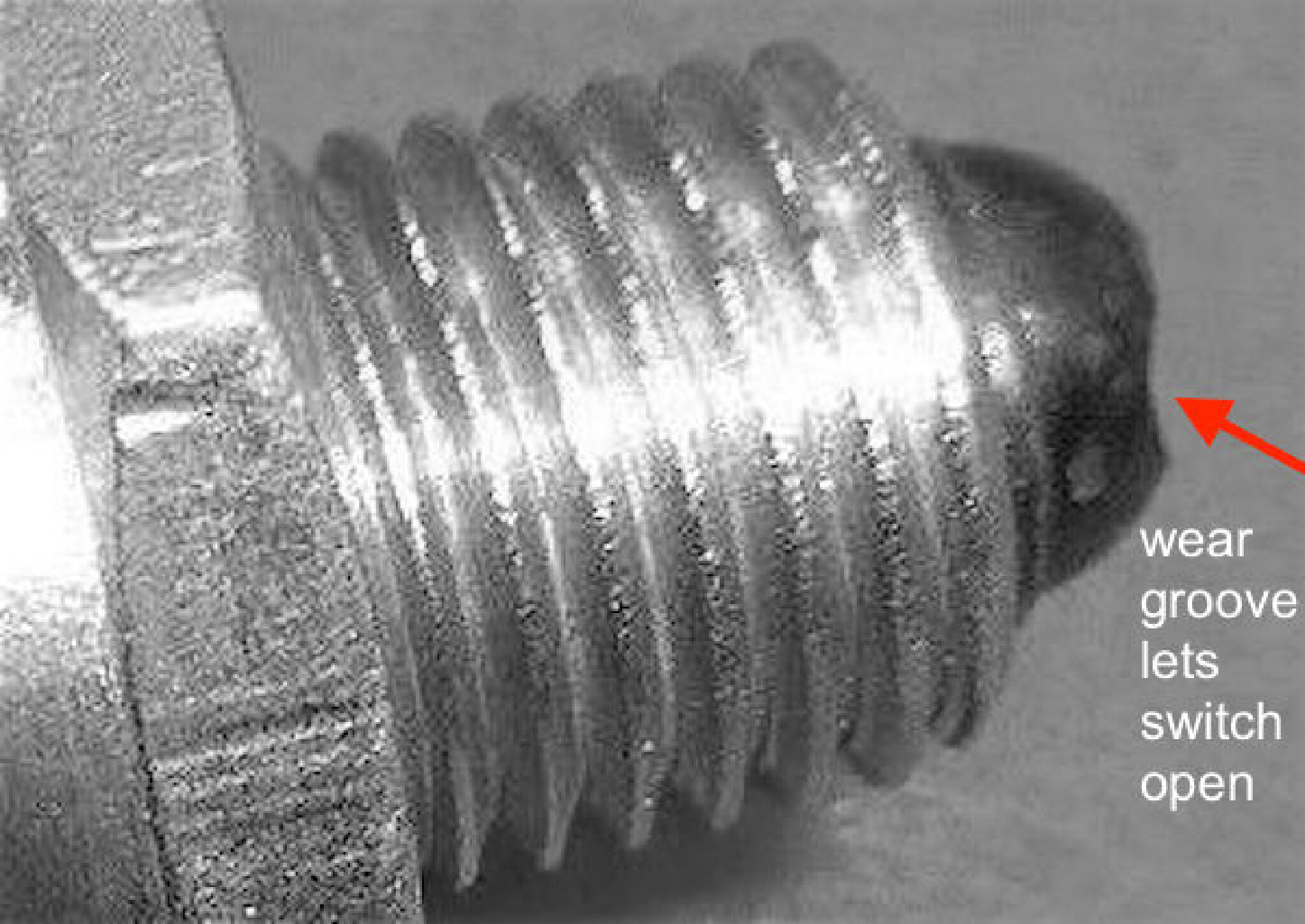
Posted on: 7/6 13:08
|
|||
|
Howard
|
||||
|
||||
|
Re: Ultramatic gearbox problem slipping direct drive clutch
|
||||
|---|---|---|---|---|
|
Forum Ambassador
|
Also check out the article starting on page 11 about the new torque converters for 52. Your 51 probably has the original design but could have the new style direct drive clutch converter if problems developed in the splines on the old style driving piston plate. If yours is still original the article mentions splines causing problems on release but as I recall there are other articles saying problems with DD engagement could be an issue if the splines on the DD plate were sticking or had developed wear or gouges.
Posted on: 7/6 9:27
|
|||
|
Howard
|
||||
|
||||
|
Re: 2262 Rear Tire Removal
|
||||
|---|---|---|---|---|
|
Forum Ambassador
|
If you did jack from the frame do you see anything pulled tight such as a brake hose or emergency brake cable that could be preventing a drop? Since the issue is on the left side how about the 5th shock/horizontal stabilizer. Could that be a repro or repaired unit that possibly doesn't have enough travel.
Posted on: 7/5 21:35
|
|||
|
Howard
|
||||
|
||||
|
Re: Unknown bumper strap
|
||||
|---|---|---|---|---|
|
Forum Ambassador
|
If there was nothing connected to the open end of the bracket but it was in a position to have something attached that could hang down and clear other parts of the body it might have been for an anti-static strap. Those were a fairly common item back in the day in areas with climate conditions where static electricity was an issue.
The straps are not as common today with tires being made with compounds that can conduct and dissipate the static fairly well but are still around. Here is a modern example. 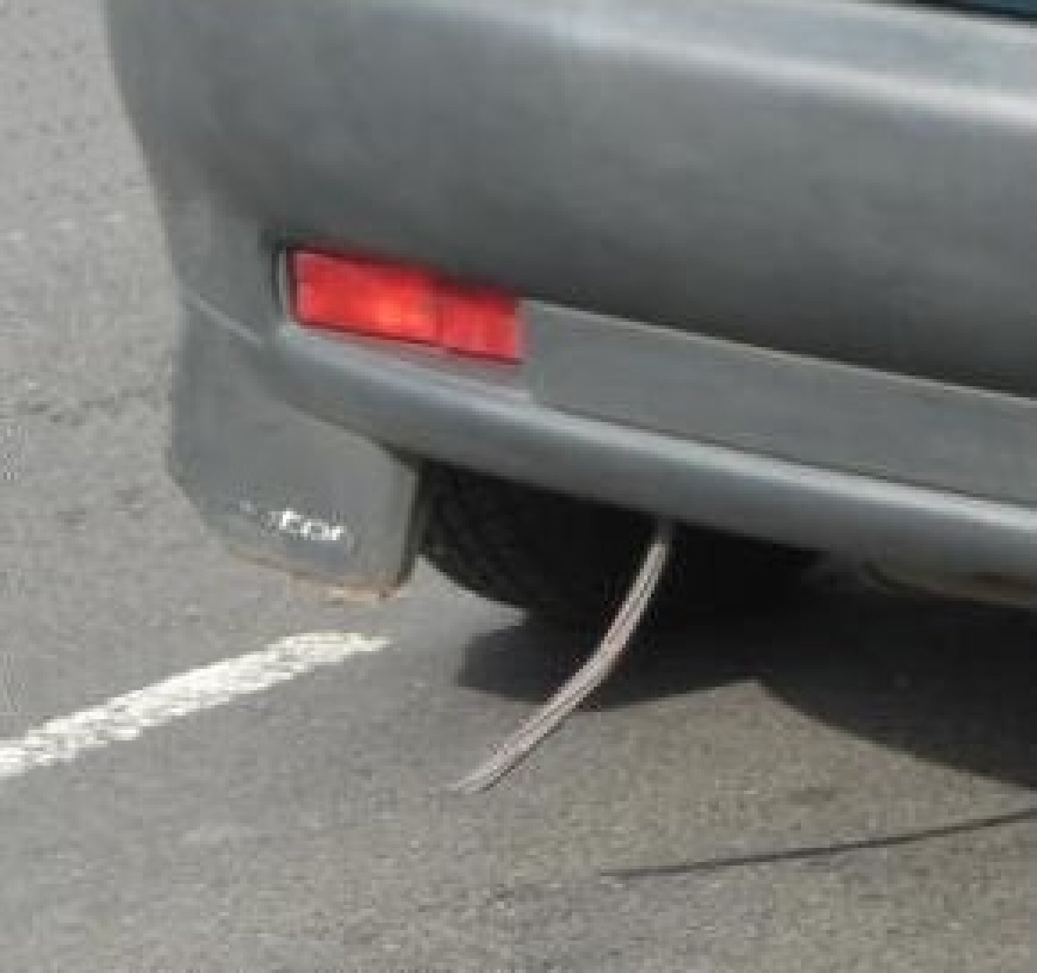 I don't see enough of the bumper to be clear on where the opening in the bumper is located or if that is where you took off one of the uprights but if it is always exposed, another possibility might be for some kind of whip antenna.
Posted on: 7/4 18:10
|
|||
|
Howard
|
||||
|
||||
|
Re: missing ignition switch?
|
||||
|---|---|---|---|---|
|
Forum Ambassador
|
It is not too terrible a project and well worth doing but can be messy and time consuming. On those engines with a front motor mount like yours there is also a good chance the rubber in the motor mount has deteriorated and let the engine drop a bit. You MAY need to use a floor jack with some wood to spread the load under the pan to lift the engine slightly. If you do need more clearance then on a 356 before raising check on both sides near the front for any small auxiliary stabilizers that are bolted to the front cross member and loosen those before raising. Once raised then figure out how and where to best block the engine a bit higher above the front crossmember so as to have enough clearance to slide the pan back and out. Remember to keep the pan edges clear of any supports. Been a while but if memory serves there may be bolts at the rear of the pan under the lower bellhousing cover so I believe that will also need to come off. When removing that it may not be evident but one of the transmission bolts at the bottom will also need to be removed to get the cover off. Once the pan starts out you may also need to turn the crank so counterweights can clear the pan baffles or front of pan as you slide it back.
When it is out, note the pan edges around the bolt holes and check them while it is off. Use a straightedge to check for any raised areas around a bolt which can happen if the bolt is over torqued and gasket was compressed too much. Use a round end hammer to gently hammer any raised hole edges back to flush or there is a good chance the new pan gasket will leak. Don't forget to clean the oil pump pickup screen while you are cleaning the pan.
Posted on: 7/3 17:41
|
|||
|
Howard
|
||||
|
||||
|
Re: missing ignition switch?
|
||||
|---|---|---|---|---|
|
Forum Ambassador
|
Congratulations. Without a filter, gravity with a couple of feet as a head should provide plenty of fuel pressure so unless you were running fuel thru the typical ceramic filter Packard used I expect you still have a carb issue you need to sort. No idea how much pressure a lift pump will supply but the stock mechanical pump on the engine puts out about 4 1/2 psi. Those old carbs cannot accept much more than 5 or 6 psi at the carb inlet or pressure will overpower the inlet valve operated by the float and gas will pour into the carb and then leak down into the manifold.
Posted on: 7/2 20:11
|
|||
|
Howard
|
||||
|
||||


