|
Re: '28 5-26 Hood Removal / Installation
|
||||
|---|---|---|---|---|
|
Just can't stay away
|
Thanks DavidM! I'm missing the described components, but should be able to fabricate serviceable replacements. Thanks for the description.
Posted on: 2014/4/7 16:58
|
|||
|
||||
|
'28 5-26 Hood Removal / Installation
|
||||
|---|---|---|---|---|
|
Just can't stay away
|
Can someone with a similar car please explain to me how the top, center-line hinged section of their hood affixes to the vehicle? Someone has clearly rigged something on mine, and I don't know if I'm missing parts or not. I'd like to return it to original form and need to know how it's supposed to work. I can't find anything reveling in the service manual or after searching the forum.
On the firewall side, there's a pin that seats in the hole above where the radiator <-> firewall support strut affixes. On the front, however, I have a hole in the back of the radiator shroud and another hole on the front of the hood. I've wondered if I'm perhaps missing a pin? If so, though, I still can't figure how it goes together since there would be no way to insert or remove such a pin with the two pieces lined up (there's only about a 1/16" gap). Do you have to disconnect the support strut, loosen the radiator and angle the shroud forward (all while holding the hood in place) in order to get a pin in both holes, and then tighten it up in place to bring things together? It seems like you'd need at least 3 people to make that happen successfully. If that's the process, I'll buy a case of beer and line up some helpers, but if anyone has experience with the process, I'd love to hear about it first. Thanks!
Posted on: 2014/4/7 11:26
|
|||
|
||||
|
Re: Solved: Vibration Damper Removal - 1928 5-26
|
||||
|---|---|---|---|---|
|
Just can't stay away
|
Absolutely. Thanks again.
Posted on: 2014/3/30 1:03
|
|||
|
||||
|
Re: Solved: Vibration Damper Removal - 1928 5-26
|
||||
|---|---|---|---|---|
|
Just can't stay away
|
Thanks for the pics easyed. Here are some pics of my earlier design damper completely disassembled and prepped for paint, grease and reassembly.
The open circular piece surrounding the hub and springs is a ribbon of brass that slides into the flywheels' inside perimeter grooves. When assembled, it forms a complete circle, and is I suspect included to prevent water ingress. The only parts I didn't separate are the brass sleeve from the hub. It doesn't want to budge, and I see no reason to force the issue. Not pictured are the friction disks (p/n #146998) of course, because I don't have them. Attach file:  (95.91 KB) (95.91 KB)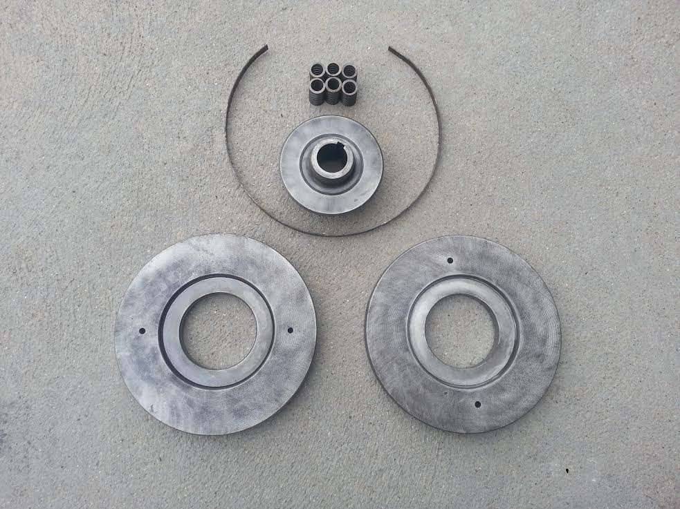 (78.74 KB) (78.74 KB)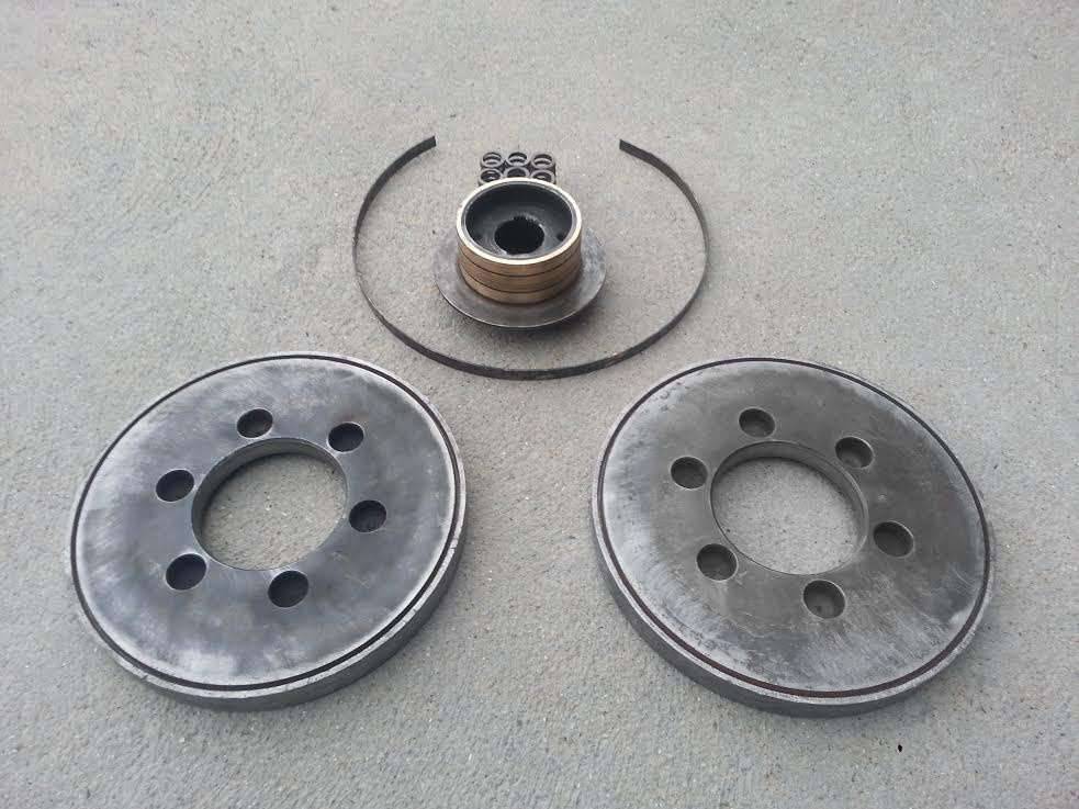 (57.98 KB) (57.98 KB)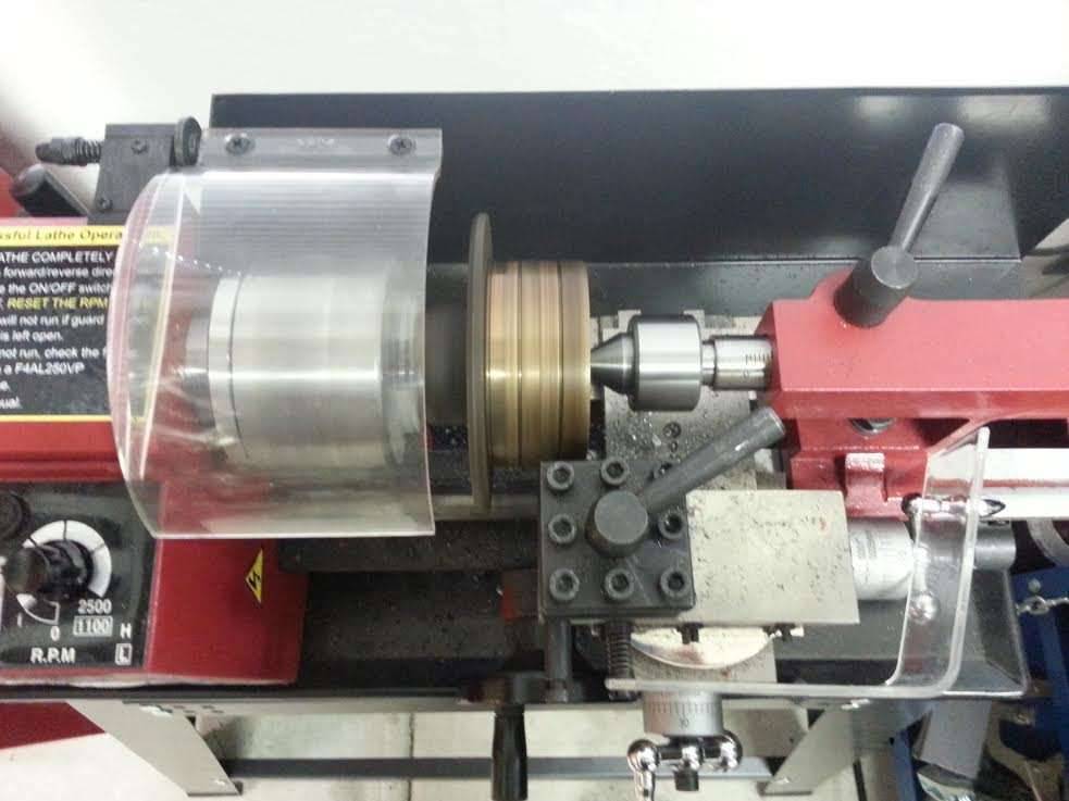
Posted on: 2014/3/29 23:57
|
|||
|
||||
|
Re: Solved: Vibration Damper Removal - 1928 5-26
|
||||
|---|---|---|---|---|
|
Just can't stay away
|
Hi easyed, It sounds like our dampers are identical. In my previous post I said "rear flywheel" when I meant "rear flange", so I can understand the confusion. I've corrected that post for posterity.
The bronze sleeve on mine is pressed onto the inner hub. It's about 1/8" thick, and you can pretty clearly see it inside of the damper's top half in the picture I posted. Prior to disassembly, which took a considerable amount of force, the flywheels were completely fused together and to that sleeve by oxidation. As mentioned, my assembly had no friction disks, front or rear, just two steel shims clearly intended to bind the whole mechanism in place. If you have a line on two p/n #146998 disks, I'd be very interested. I assumed those would be unobtainable.
Posted on: 2014/3/29 8:29
|
|||
|
||||
|
Re: Solved: Vibration Damper Removal - 1928 5-26
|
||||
|---|---|---|---|---|
|
Just can't stay away
|
Hi easyed, My interpretation of this particular unit's functionality is that the rear flange, which is indeed keyed onto the hub, is locked in sync to the crank, but the outer flywheels are (or at least should be) free to move on the hub in response to engine pulses and are pressed against the drive pulley / rear flange by the 6 springs. A friction disk on the front between the damper and pulley would certainly make sense, but none was installed on mine when removed (just the two a fore mentioned steel shims).
Rather than lock it up as claimed in my last post, I think perhaps I'm going to CNC two 0.025" aluminum shim rings to place between the damper and pulley. That should impart some friction while still affording functionality. My caliper tells me that something with a 3-1/8" ID x 4-5/8" OD should work nicely...
Posted on: 2014/3/28 17:08
|
|||
|
||||
|
Solved: Vibration Damper Removal - 1928 5-26
|
||||
|---|---|---|---|---|
|
Just can't stay away
|
Huzzah! I got the damper off last night without having to pull the engine. The heavier duty puller worked, and once done, the timing / front engine cover is trivial to remove.
As theorized, the damper is pressed together and can be disassembled by removing the flywheels from the center hub. Mine at least is comprised of 3 main pieces + 6 springs: A front and rear flywheel held apart by springs, and a center hub with a flange on the rear. When new, I suspect the flywheels were relatively simple to separate and slide off of the hub, so the service manual doesn't detail the process. After 86 years however... Later dampers may be more complex, but I wouldn't hesitate to open one of these if you're faced with the same situation. There's not much going on inside, and reassembly should be trivial. The caveat being that I suspect they don't work very well, even when new. My two halves were completely fused, so it was, in effect, just a chuck of iron on the crank. That's not entirely useless though, as its inertia will offer some damping. Bottom line, if the paint seam between the halves of your damper is unbroken, you too just have a chunk of iron bolted to your crank. One observation I'd offer though, is that there may be disadvantages to having the damper work as designed. As mentioned, whoever rebuilt my engine placed two shims between the drive pulley and the front flywheel to effectively lock the damper. Without those, there is a 1/32" or so gap, which I believe intentionally exists to allow the flywheels some clearance to rotate. The trouble is, this is a very unsophisticated design, and there are no bearings or friction plates used. Any rotation of the flywheels is almost certainly going to subject the inner hub and drive pulley to metal on metal wear. I never noticed the damper wasn't working before, so I think I'll again lock it up with a shim upon reassembly. *** Asterisk *** My understanding of how this things works could be completely and utterly wrong, so use your own judgement! In closing, the moral of this story is, as with so many others: When in doubt, use a BFH. Thanks to everyone who offered suggestions! Attach file: (54.41 KB) (49.21 KB) (49.21 KB)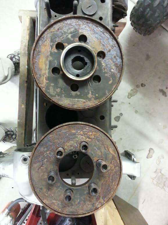
Posted on: 2014/3/28 13:16
|
|||
|
||||
|
Re: Vibration Damper Removal - 1928 5-26
|
||||
|---|---|---|---|---|
|
Just can't stay away
|
Thanks Tom. Forgive my ignorance, but could you explain what you mean by "selective spacer"?
All I want to do is change the timing cover gasket to fix an oil leak. With the exception of this damper, the cover is free and clear, but if the motor has to come out, so be it. That seems an awful lot of work to go through though, and I can't imagine that's what the engineers at Packard had in mind. I've honestly thought it may be easier to simply pull the cover away as far as possible to prep the two surfaces, slide a gasket in, and bolt it back together. It would certainly work, but that cover is about the only part of my engine that's messy and poorly painted. I'd really like to get it off, cleaned thoroughly and resprayed.
Posted on: 2014/3/27 20:25
|
|||
|
||||
|
Re: '28 526 Fender bead
|
||||
|---|---|---|---|---|
|
Just can't stay away
|
My '28 5-26 has a 3/16 bead on all 3 of the running boards' 4 sides (excluding the exterior side of course).
Attach file: (32.84 KB)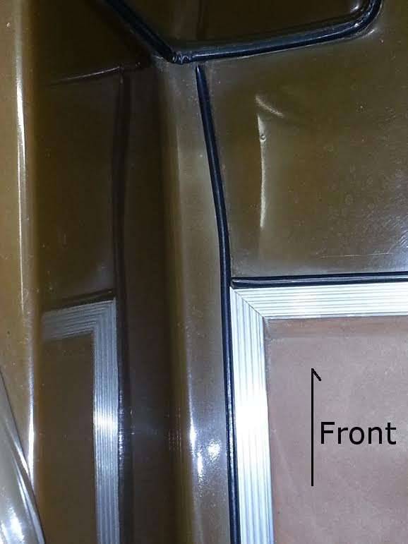 (26.79 KB) (26.79 KB)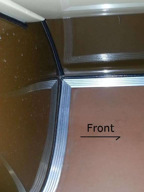
Posted on: 2014/3/27 19:57
|
|||
|
||||
|
Re: Vibration Damper Removal - 1928 5-26
|
||||
|---|---|---|---|---|
|
Just can't stay away
|
Thanks jwogec! Is there anything related to the damper on the next page? Some of the pictured part numbers aren't cited. I assume the 526 is the same as the 626 (not a safe assumption though really), but in addition to the two flywheels, there should be a flange and hub listed since those two flywheels don't slide onto the output shaft directly (the opening diameters are clearly too large). p/n #158729, for instance, looks a likely candidate. I have motor #163870 fwiw. Thanks again!
Posted on: 2014/3/27 13:06
|
|||
|
||||


