|
Re: Torsion-Level Problem
|
||||
|---|---|---|---|---|
|
Forum Ambassador
|
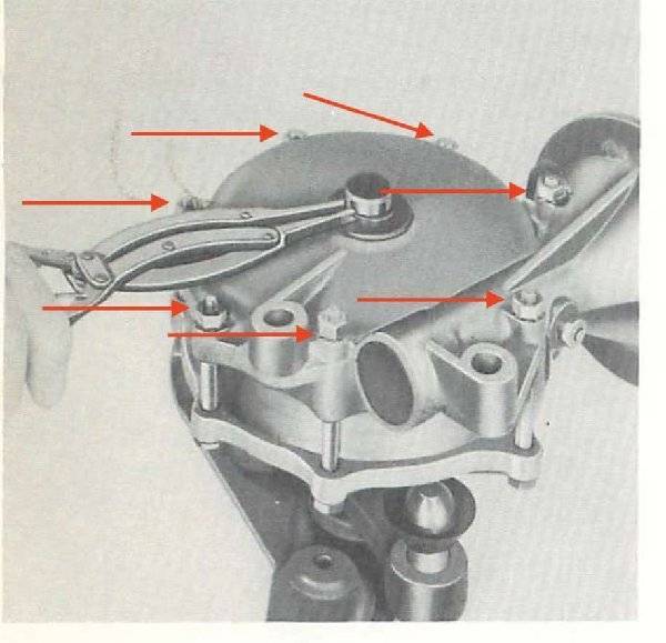
If you cannot use the worm shaft to move the compensator the other way to unload the bars is to LOOSEN but do not remove the 7 bolts holding the two halves of the compensator together. The planetary ring rests in a groove on either side and is held by friction. Once the halves are loose enough the tension on the bars will rotate the ring in the housing groove until the bars find a neutral point. When doing the procedure be sure to keep your hands away from the center links because depending on how loose the ring gets it may start to suddenly release and things can move quickly.
I don't remember the clearance for the transverse bar screws at the compensator end but since you are replacing them you will most likely want to disconnect the transverse bars at the short bar end and remove everything all together. Depending on your car and the way it is supported when working on the compensator, the neutral point when load is off may want to rotate the ball links on the end of the short bars sufficiently into the frame that you will not be able to get a drag link socket on the screws holding the transverse bars to the links. If that happens, to prevent the larger issue of not being able to move the links back to a working location I have found it helps to wire or tape a small wood block approx 4x4" inside the frame on each side as insurance the links will hit that first and can not swing into the frame so far the screws are unable to be accessed. Even though there might still be tension on the short bars if they hit the blocks there will be none on the transverse bars or compensator and things can still be removed. Here is a paragraph from bulletin 55-T12 instructing mechanics how to unload the bars if the worm drive was not operational and another illustration showing the bolts that need to loosen.
Posted on: 2018/5/8 18:32
|
|||
|
Howard
|
||||
|
||||
|
Re: Torsion-Level Problem
|
||||
|---|---|---|---|---|
|
Quite a regular
|
Perfect!
Posted on: 2018/5/9 14:04
|
|||
|
||||
|
Re: Torsion-Level Problem
|
||||
|---|---|---|---|---|
|
Quite a regular
|
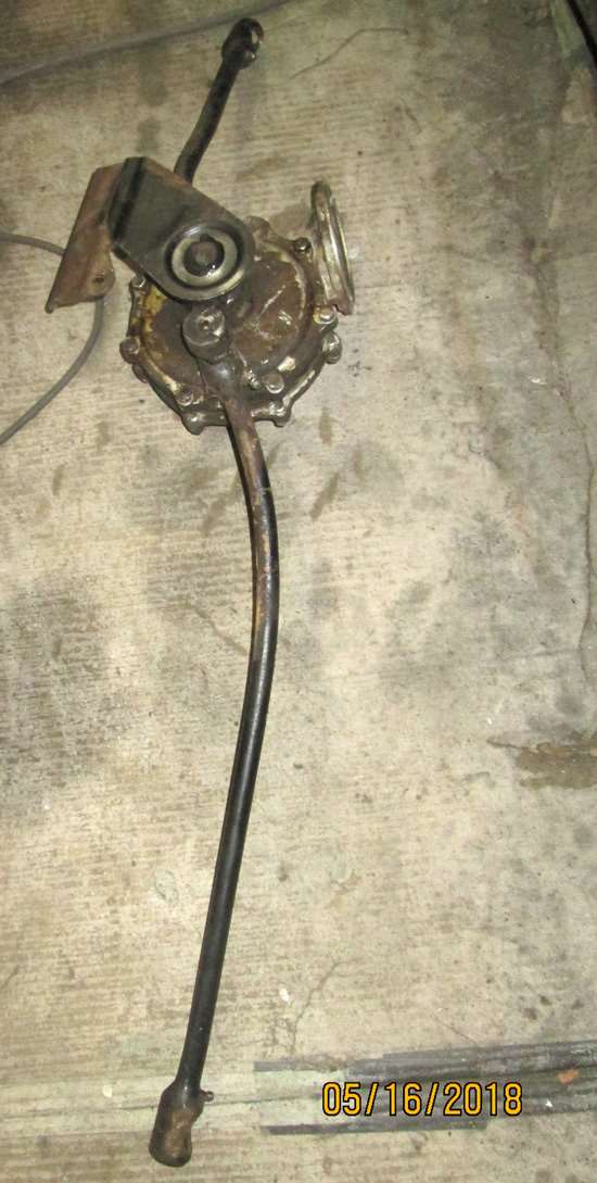
Finally got the compensator off the Clipper. It wouldn't unload as recommended so I had to gingerly release the tension by loosening the mounting. Luckily there was not a great deal of tension and I'm still in one piece. My next step is to disassemble the unit to see what happened. I have a replacement compensator and arms thanks to Mike Dulinski. My concern now is how does the main shaft index on the limit switch cam? I'm hoping it can only go in one way but there is no information in the service bulletins or shop manual that I can find. Is there any other source that shows a rebuilding process?
Posted on: 2018/5/17 0:23
|
|||
|
||||
|
Re: Torsion-Level Problem
|
||||
|---|---|---|---|---|
|
Forum Ambassador
|
55 internals didn't matter because of the external limit switches so there was no detail given. With the cam operated limit switches, 56 has a milled off spline on the output link and a wide space in the cam so the two will only go together one way.
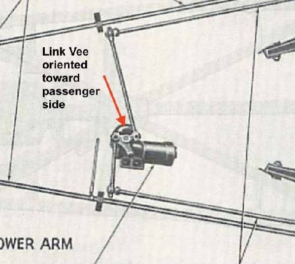
Orientation when assembling back in the compensator and the car is important but is the same as the birds eye view (fig 21) the SM shows for 55. The sort of Vee shape of the link is pointed toward the passenger side, long bar on the rearward ball.
Posted on: 2018/5/17 1:29
|
|||
|
Howard
|
||||
|
||||
|
Re: Torsion-Level Problem
|
||||
|---|---|---|---|---|
|
Quite a regular
|
Thank you!
Posted on: 2018/5/17 13:47
|
|||
|
||||

 (29.42 KB)
