|
Re: wiring questions
|
||||
|---|---|---|---|---|
|
Webmaster
|
I would think if this indeed caused that battery drain you are claiming then GM would not have wired millions of cars this way from 1968->mid 80's.
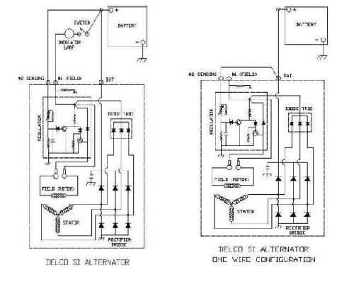
Excerpt From Hemmings Motor News Online: hemmings.com/hmn/stories/2007/03/01/hmn_feature30.html "Many enthusiasts wishing to convert their 12-volt generator system to a more reliable alternator system prefer to use the Delco 10-SI alternator to make the conversion easy and inexpensive. Most of these conversions focus on the use of a Delco single-wire 10-SI alternator; however, a two-wire will work just as easily with a little adaptation. You can buy a new two-terminal alternator connector from just about any aftermarket parts supplier (GM# 36294493). The terminals on the plug-in for a 10-SI are marked 1 or "R" and 2 or "F." Terminal 1 or "R" is connected to the accessory terminal on your ignition switch through the use of a resistance wire or an inline fuse for overload protection. This terminal may also have a jumper wire spliced into it, which activates a dash light when alternator voltage is too low. Terminal 2 or "F" is normally connected through a junction block to the battery "hot" wire to the ignition switch. However, in this case, the wire from terminal 2 should be attached to the large battery stud on the back of the alternator, which is the same connection for your battery positive wire." Also if you look the attached diagram from AutoReWire.com, you can see that the one-wire version simply bridge termial 2 to battery feed internally. Perhaps you are confusing the switched dash light circuit which also acts as the exciter, with the voltage sensing terminal.
Posted on: 2008/9/4 23:25
|
|||
|
-BigKev
1954 Packard Clipper Deluxe Touring Sedan -> Registry | Project Blog 1937 Packard 115-C Convertible Coupe -> Registry | Project Blog |
||||
|
||||

Happy 4th of July and welcome to Packard Motor Car Information! If you're new here, please register for a free account.
 (32.26 KB)


