|
Re: Jeff's 48 Custom 8 Victoria Project
|
||||
|---|---|---|---|---|
|
Home away from home

|
Thanks! The fun stuff is coming up next, as I will start putting things back on the car.
Jeff
Posted on: 2013/10/21 22:57
|
|||
|
||||
|
Re: Jeff's 48 Custom 8 Victoria Project
|
||||
|---|---|---|---|---|
|
Home away from home
|
My thinking was that it's finally time for the fun part of the project: putting the car back together, but the fun was short lived. One of the first orders of business was to bend up some new hydraulic lines, and I hate bending lines! Dell suggested using flexible plastic lines, and I will recommend that to the owner for when the time comes to finish the job. There's a big mess of lines under the back seat that will need to be replaced. I just did the engine compartment, and the lines that run behind the firewall pad. Once that unpleasantness was out of the way, it was time to install a nice new wiring harnesses that the owner bought from Rhode Island Wiring. They did a very nice job making up the harnesses. There were only a few minor fitment issues that I plan to tell them about, so that they can make some improvements for the next 22nd series owner who needs new wiring. Attaching all the components to the firewall was basic nuts and bolts work. I installed stainless screws in the holes that the factory had plugged with wads of dum-dum. These holes would normally be for the upper row of firewall pad retaining pins, but due to the hydraulic lines being in the way, the pad sits too far out to install the pins. I used a bit of artistic license on the voltage regulator and overdrive relay: orange for Autolite and dark blue for Delco. The colors show much brighter in the pictures than in person, but I may have to redo the regulator in black or gray. I'll see how things look when the hood is on. I was just trying to add a little visual interest to an otherwise mostly black engine bay.
A big milestone was getting the dash back together and installed in the car. That went fairly smooth, though it's a tight fit to get it past the windlace. Also, I found that it's best not to install the wiper control until after the dash is in place. I bought a roll of anti-squeak padding from Dennis Carpenter to replace the ratty old stuff. It's a bit narrower than what Packard used, but worked out fine. With the dash in place, I could feed the engine bay wiring through the firewall and get it hooked up. I replaced the original metal and cardboard terminal block with a modern plastic one made for semi-trailers. It has a fourth terminal that can be used for fog lamps if the owner desires to install them. I had an extra instrument lamp switch that I installed in the fog lamp position. To add fog lamps, wires will only need to be run from the terminal block to the lamps. One of the upper bumper halves was off of a car with fog lamps, so it has the mounting hole drilled in it. Next to go on were the hood latches and control rods. The springs on the latches were quite challenging to install, though I did manage to come up with a decent technique to get them in place. The steering column was also harder to get in than expected. I installed it in the car piece by piece, but I think it would have been better to assemble it first, then put it in. It's a real tight fit to get the long column tube through the upper jacket. The paint that I had applied to the tube got all scratched up from sliding it through. I tried to polish out the scratches, and ended up turning the satin black paint to gloss black. The last thing to go on was the front lights and related wiring. Somehow, I managed to misplace most of the screws for the parking lamp bezels. Hopefully they will turn up soon, or I'll have to buy new ones. It's finally looking like I'm making some real progress. One would think that it won't be long before the engine is ready to go back in. October 2013. Packard starts to go back together. Attach file:  (77.42 KB) (77.42 KB) (85.34 KB) (85.34 KB)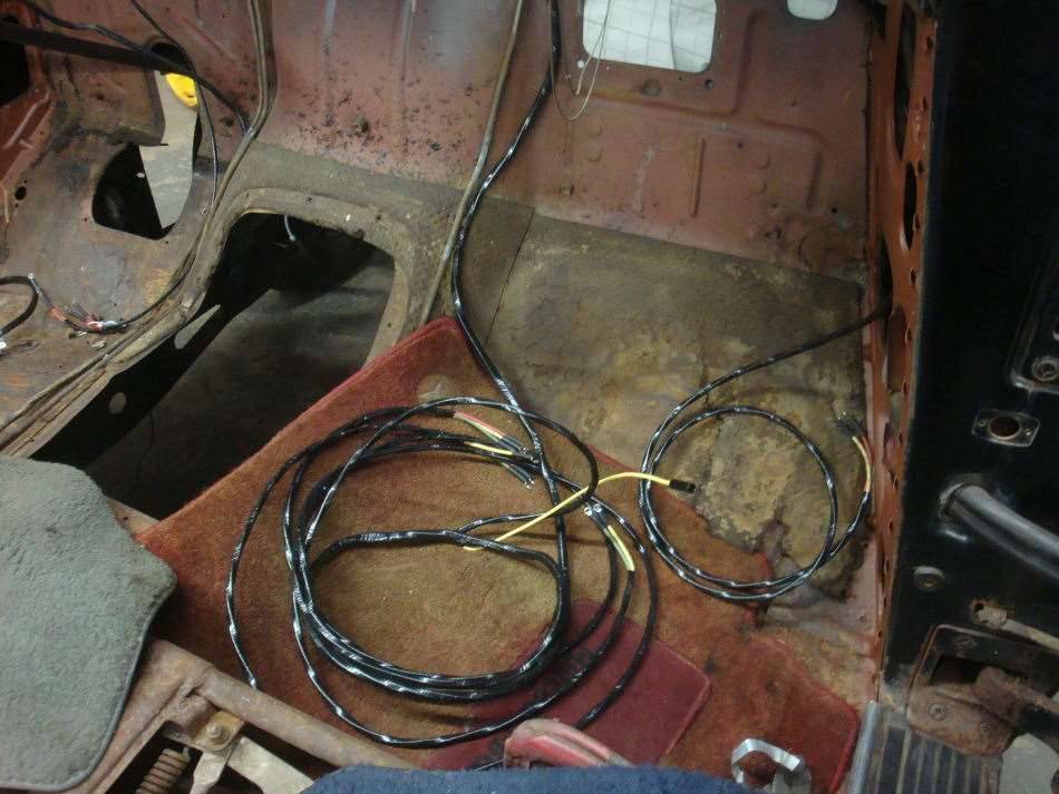 (78.29 KB) (78.29 KB)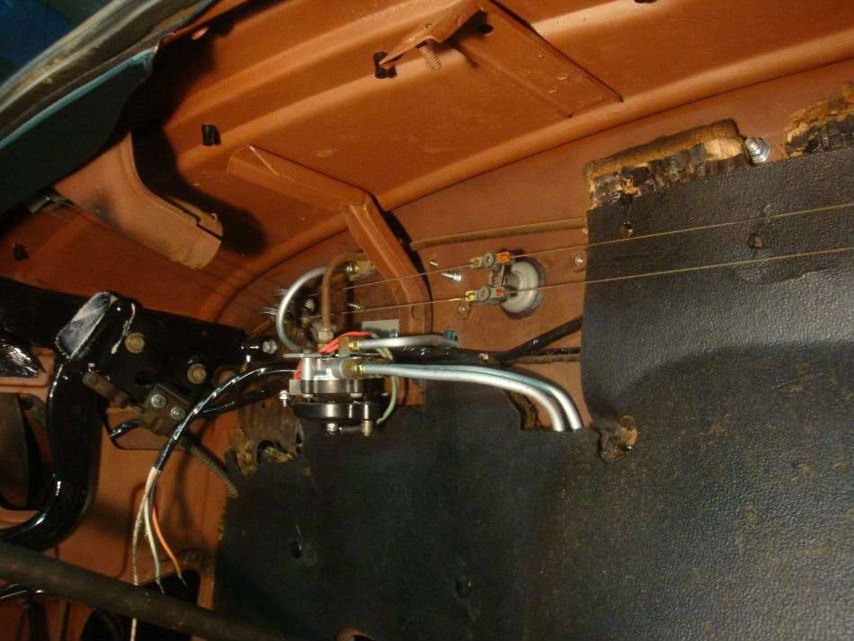 (106.91 KB) (106.91 KB) (80.08 KB) (80.08 KB)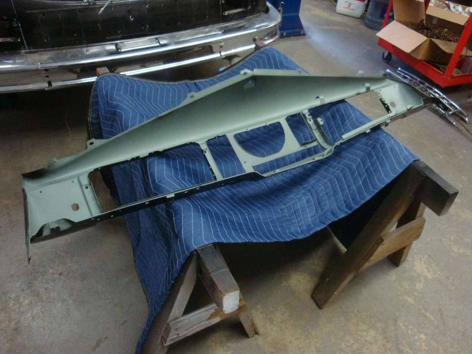 (100.56 KB) (100.56 KB)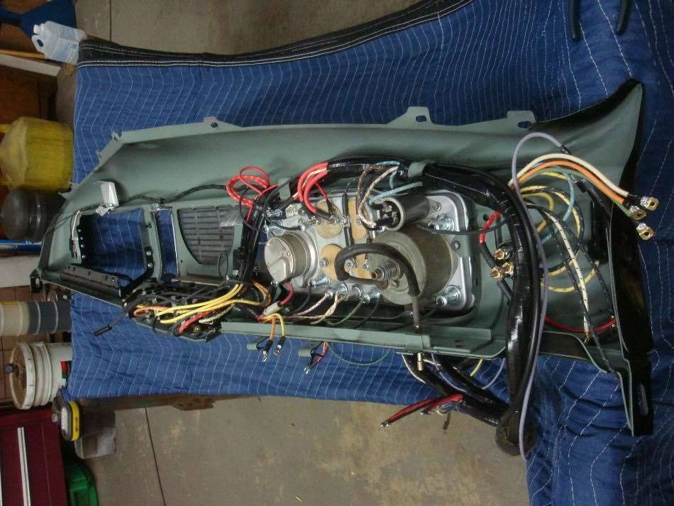 (90.29 KB) (90.29 KB)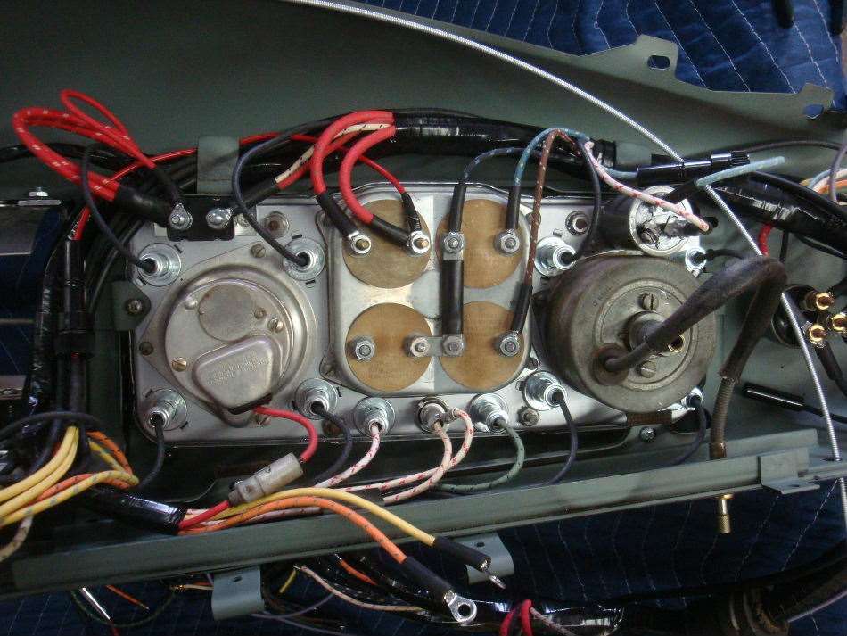 (85.36 KB) (85.36 KB)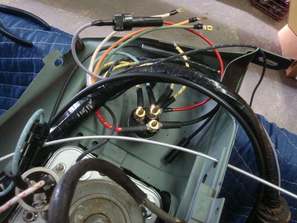 (91.30 KB) (91.30 KB) (88.80 KB) (88.80 KB)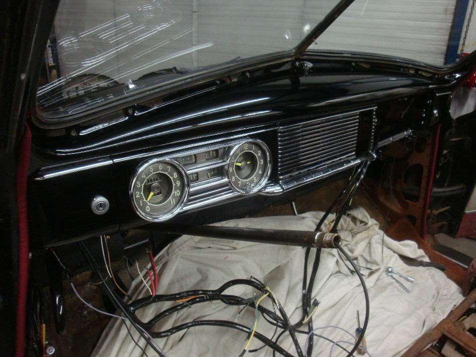 (102.63 KB) (102.63 KB) (77.04 KB) (77.04 KB) (54.79 KB) (54.79 KB)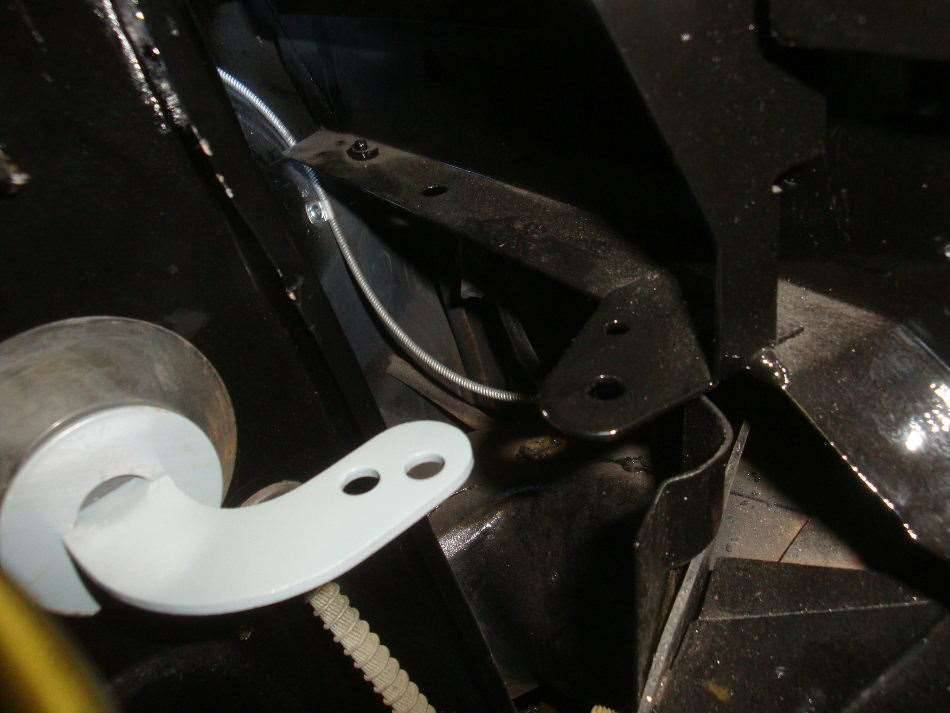 (83.69 KB) (83.69 KB)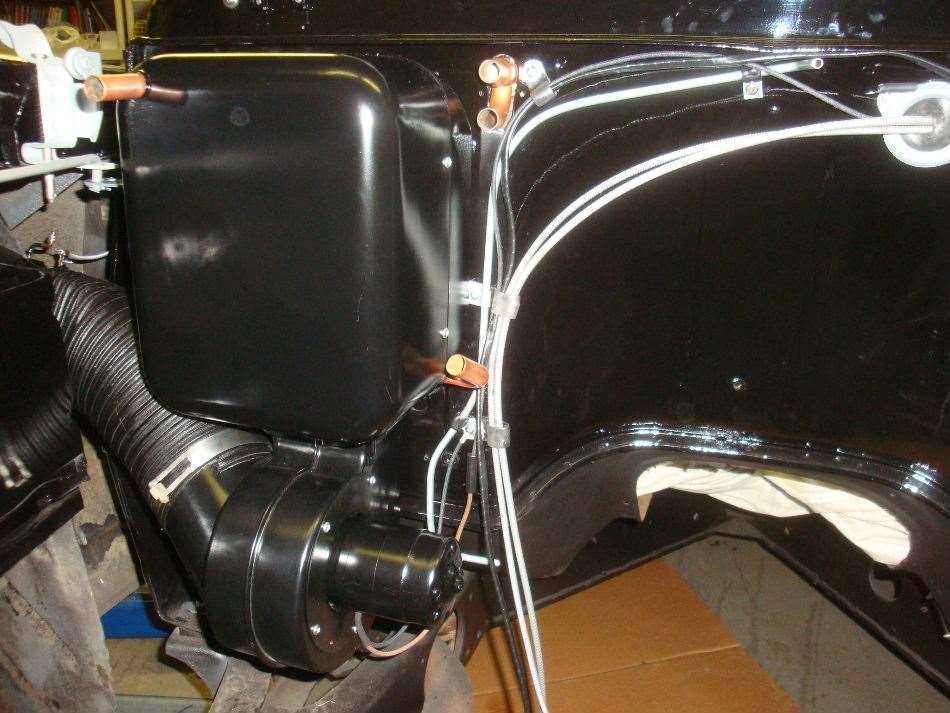 (83.46 KB) (83.46 KB)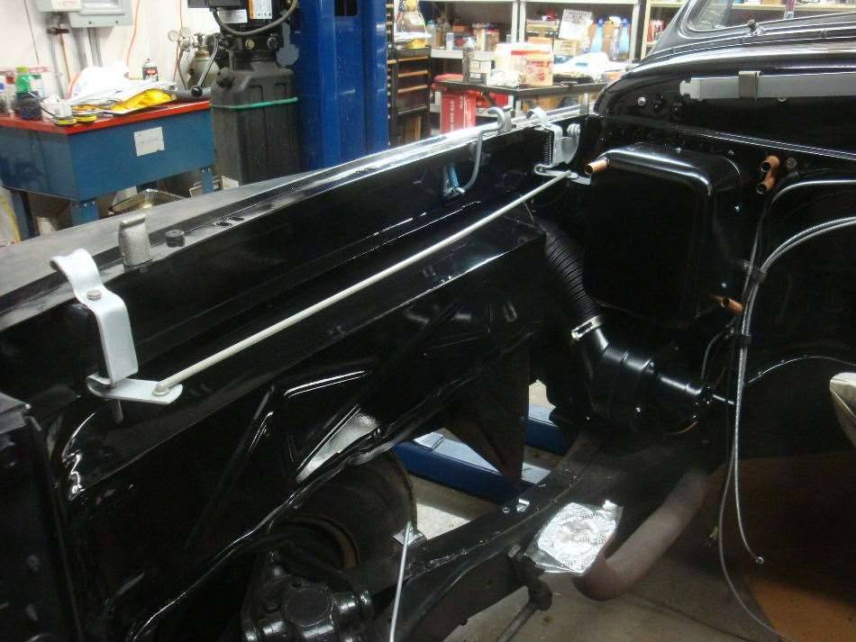 (82.16 KB) (82.16 KB)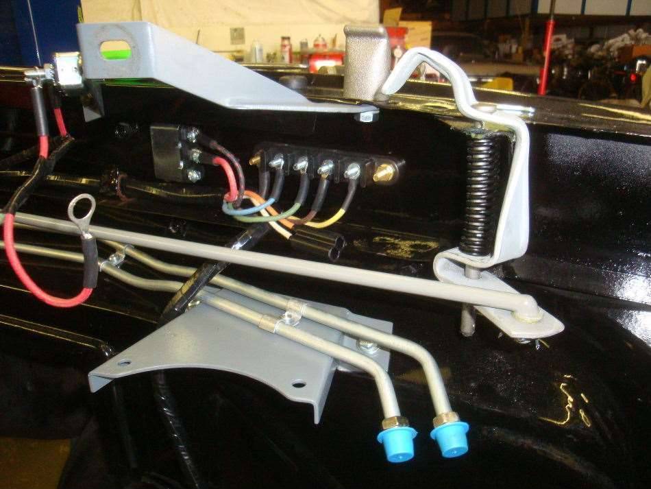 (77.02 KB) (77.02 KB)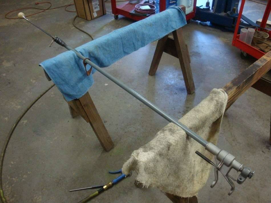 (72.63 KB) (72.63 KB)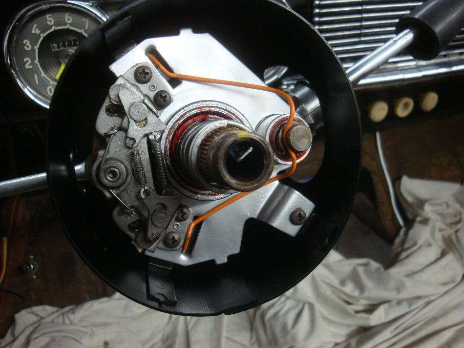 (93.27 KB) (93.27 KB)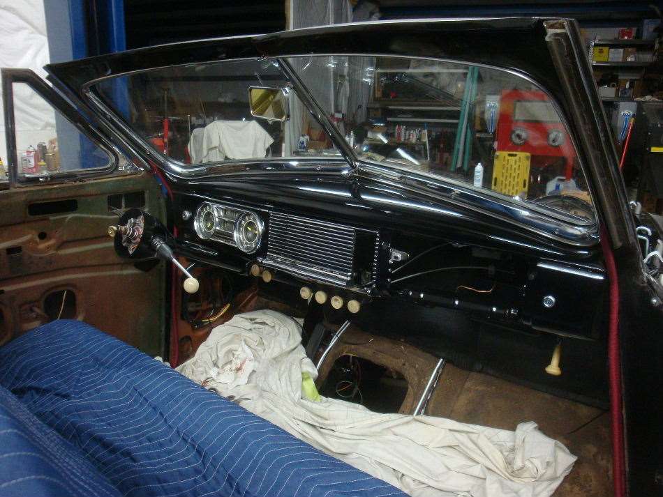 (101.75 KB) (101.75 KB) (99.49 KB) (99.49 KB) (78.31 KB) (78.31 KB)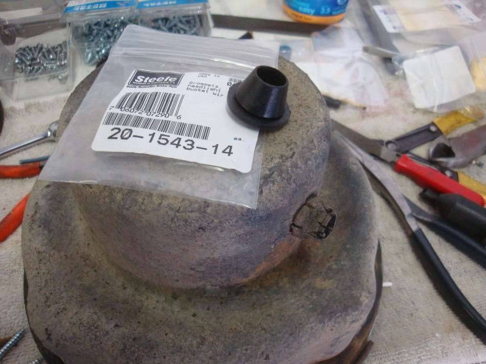 (92.37 KB) (92.37 KB)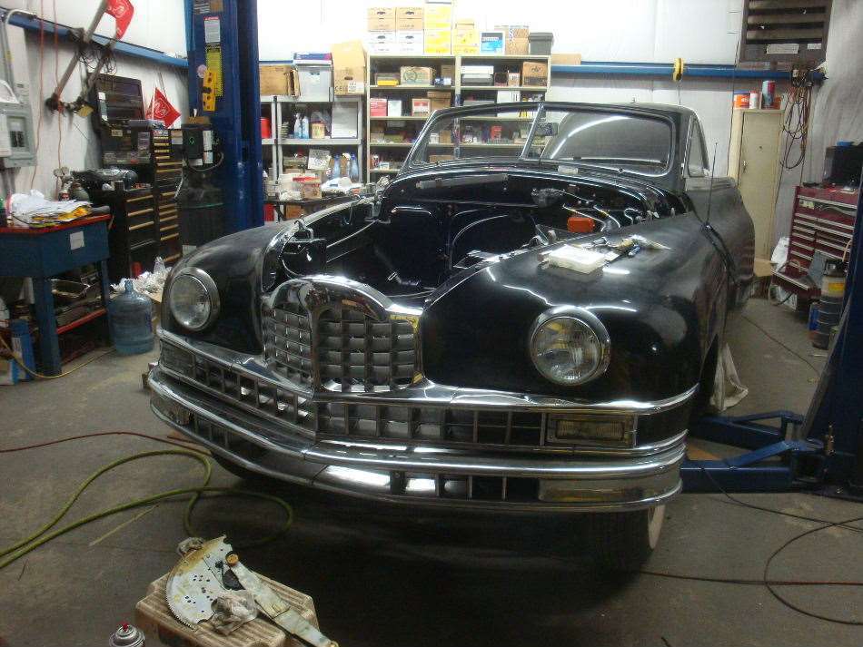 (64.76 KB) (64.76 KB)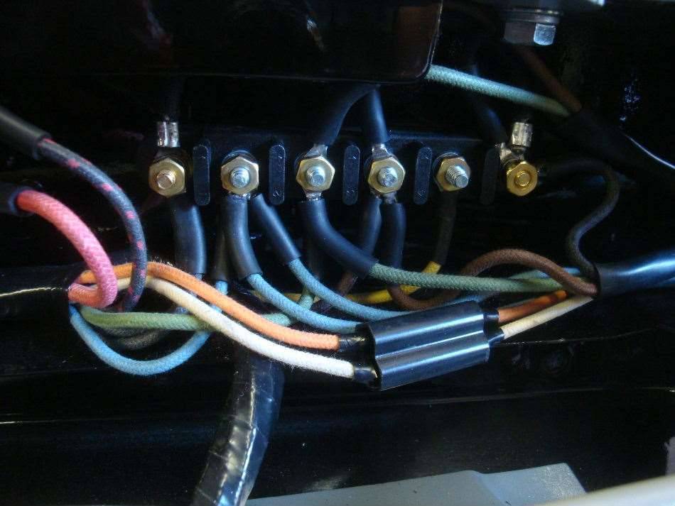 (71.52 KB) (71.52 KB) (95.33 KB) (95.33 KB) (89.31 KB) (89.31 KB)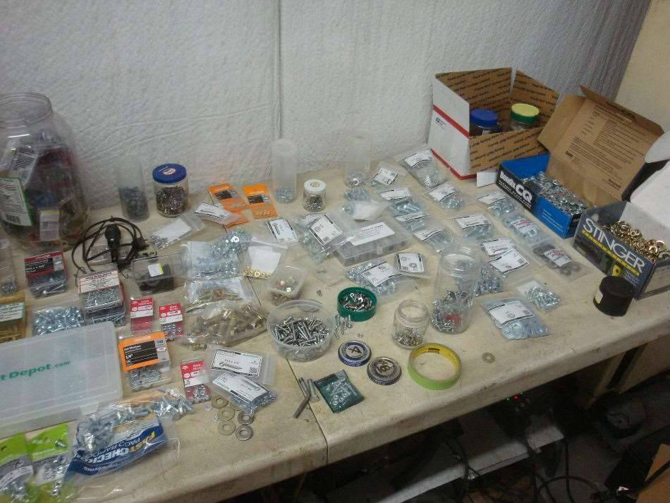
Posted on: 2013/10/26 2:40
|
|||
|
||||
|
Re: Jeff's 48 Custom 8 Victoria Project
|
||||
|---|---|---|---|---|
|
Home away from home
|
I took the transmission apart a couple months ago. I had planned to put it right back together, as I had a gasket kit and new seals ready to go. I found that the input shaft front bearing and rear transmission bearing were a bit on the rough side and should be replaced. According to the service manual, my overdrive balk ring wasn't up to spec either. The trans would have to wait till I gathered up the required parts before it would go back together.
The Packard three speed transmission is fairly easy to work on, and doesn't require much in special tools to take it apart and put it back together. The service manual shows a dummy shaft tool used for holding the needle bearings and thrust washers for the cluster gear in place during installation. The Cluster shaft diameter is .885", which just happens to be exactly the same as a piece of ?" copper pipe. There are other manual trans's out there that you don't need to use the dummy shaft, buts it's a necessity on this one because you need to push the cluster shaft to the bottom of the case in order to install the input and output shafts. Then you pry the cluster up into place and install the cluster shaft. (Or as I did, turn the trans upside down, and pry the cluster down). The manual is short on pictures and the parts book picture is lousy, so I would recommend taking very good notes when taking things apart. Though the trans is easy, the overdrive presents a challenge. There is one snap ring that's a real bugger to get out. Access to the ring is hindered by an oil slinger, and it's really tough to open the ring enough to get it off the shaft. Another "special tool" that helped out was a plastic sleeve that came on a spark plug that I bought some time in the past. It was part of the packaging to protect the tip of the plug from damage. Probably a Bosch or Japanese brand. I cut the sleeve lengthwise, and it really helped to install the shifter shaft seals and the felt seal for the overdrive lockout lever. The service manual and one of the service bulletins states that the drag on the balk ring should be around 5 pounds. I measured mine, and was between 1 and 2, so I bought a brand new ring from Max Merritt. The new ring is about the same as the old, so I'm going to have to say that the 5 pound specification is incorrect. I took both the overdrive solenoid and overdrive governor apart. The solenoid has a bunch of contacts in it that were all in need of cleaning. The governor had high resistance between one of the contacts and the metal that it attached to, so I had to solder the contact to the metal piece. I now know that the trans should be painted engine color, but I painted it before I found that out. I painted it based on what I found on it while cleaning it. As far as I could tell, there was black paint on the case before the carb cleaner removed it, and the overdrive unit was obviously an orange-red color. September to November 2013. Refurbish transmission and overdrive Attach file: (67.12 KB)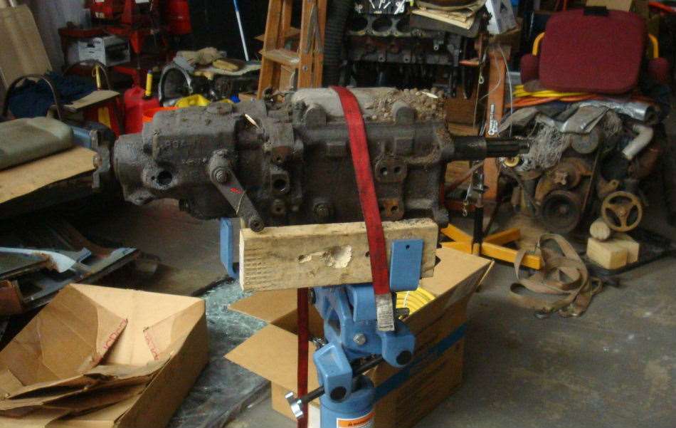 (82.59 KB) (82.59 KB) (81.64 KB) (81.64 KB) (82.99 KB) (82.99 KB)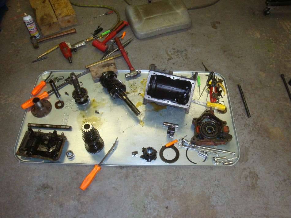 (85.16 KB) (85.16 KB)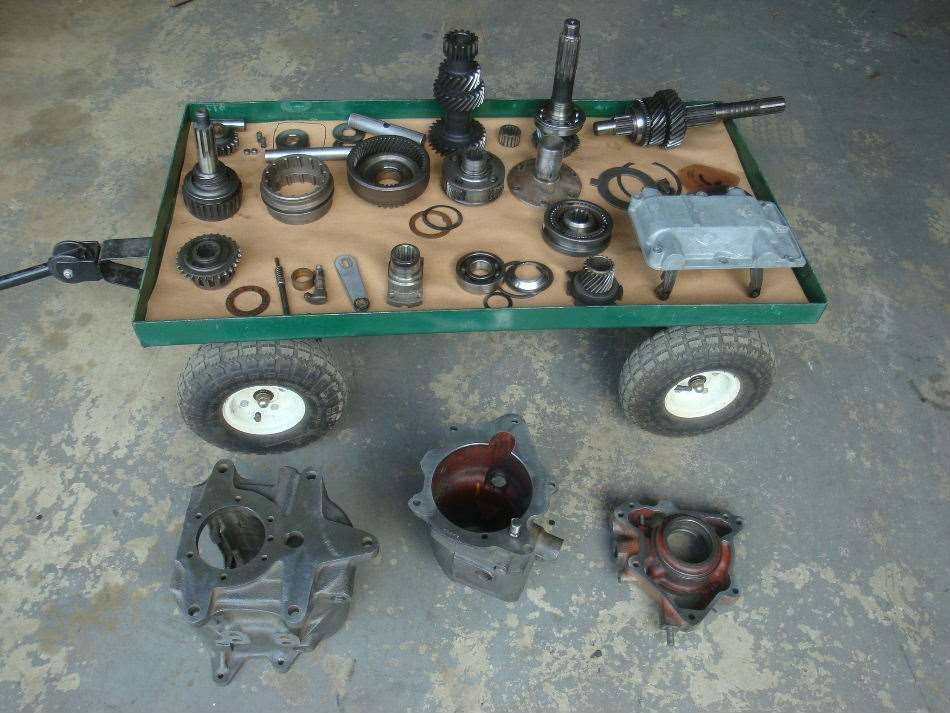 (66.27 KB) (66.27 KB)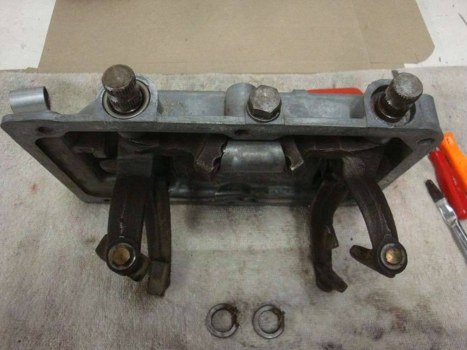 (54.39 KB) (54.39 KB)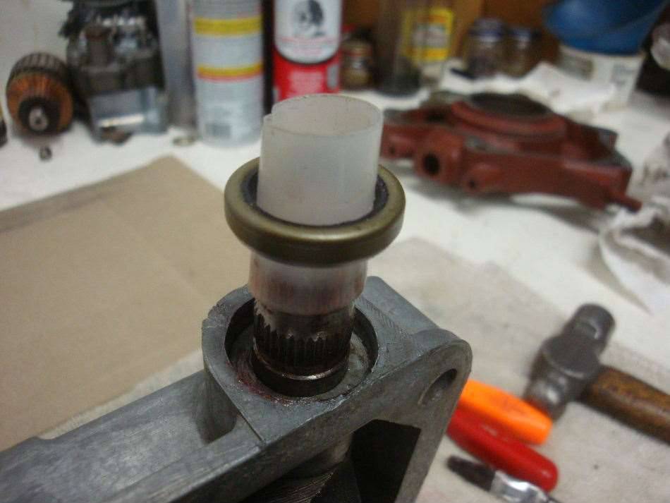 (81.99 KB) (81.99 KB)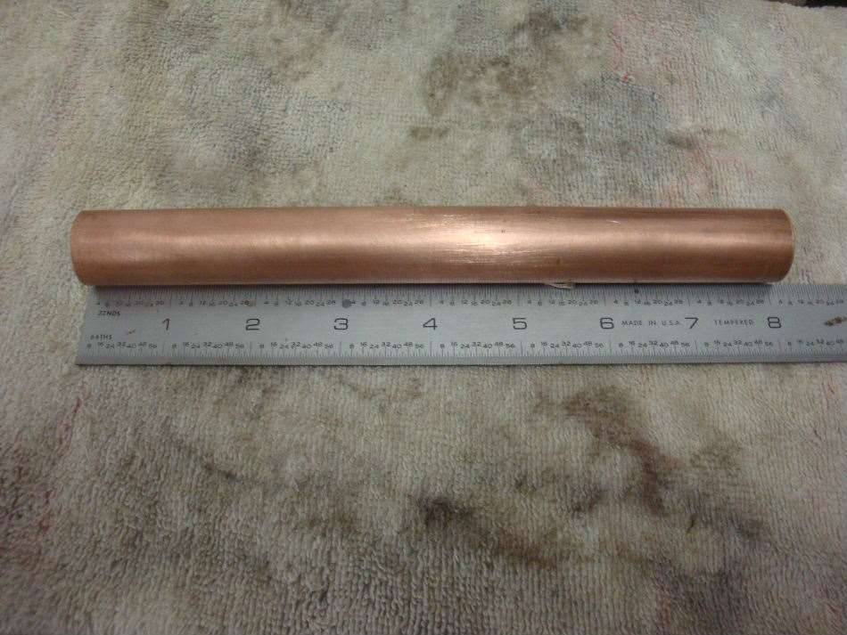 (99.72 KB) (99.72 KB)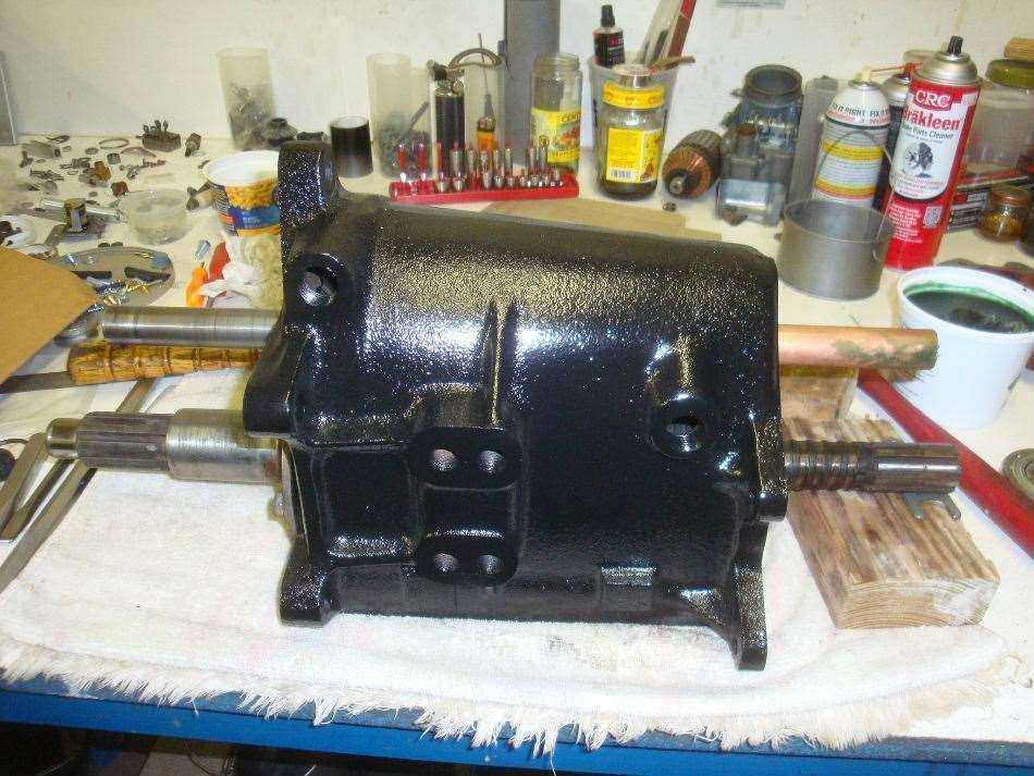 (63.09 KB) (63.09 KB)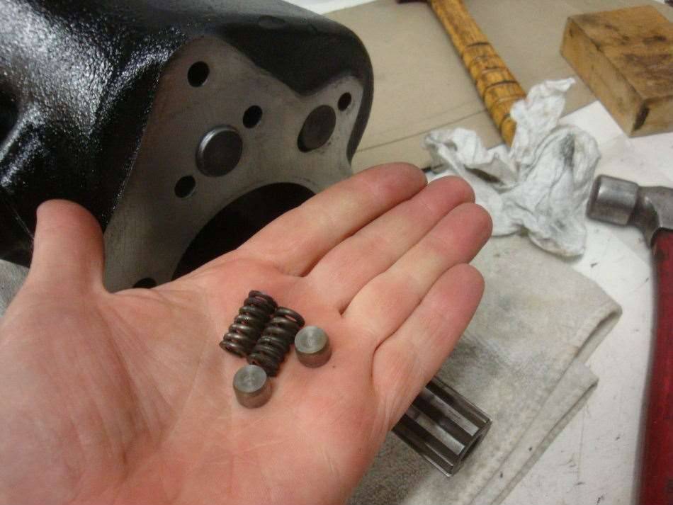 (79.66 KB) (79.66 KB)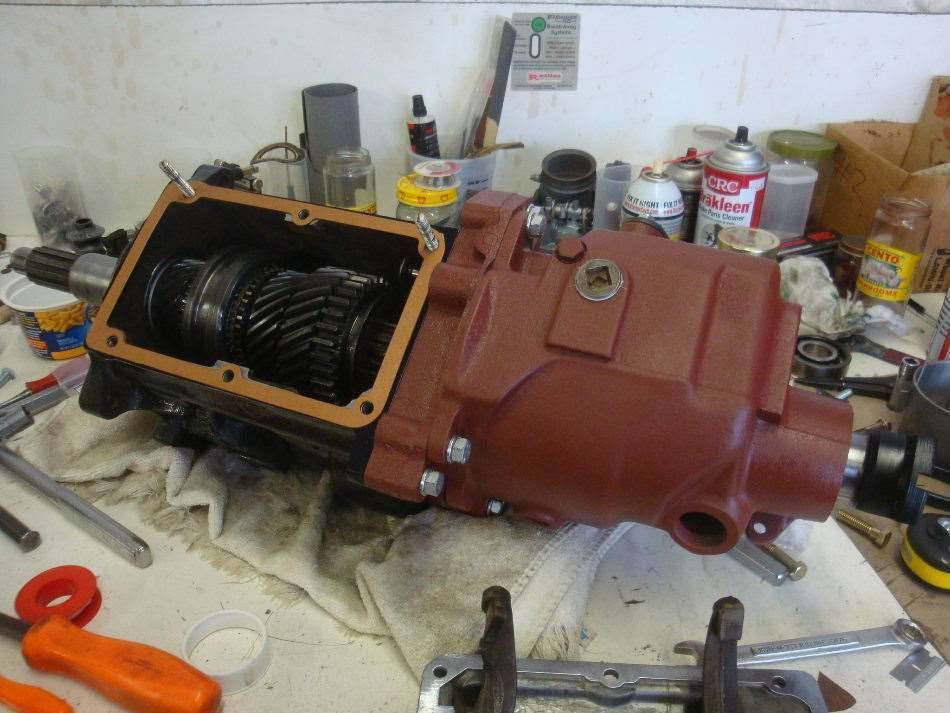 (83.01 KB) (83.01 KB)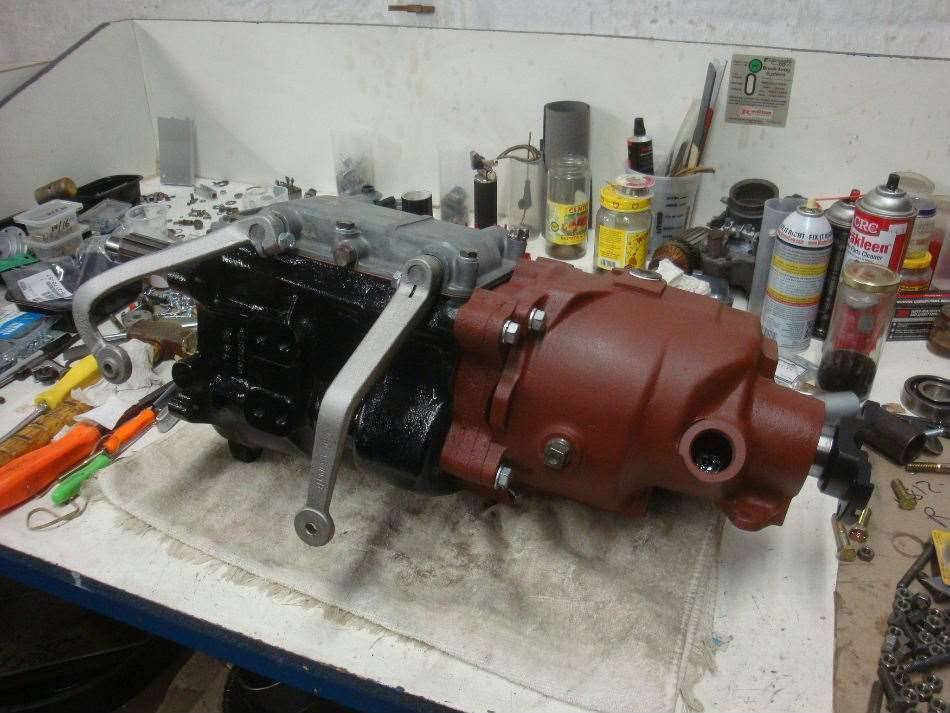 (77.92 KB) (77.92 KB) (95.67 KB) (95.67 KB)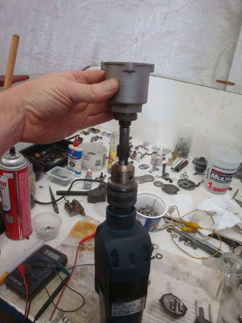 (67.20 KB) (67.20 KB)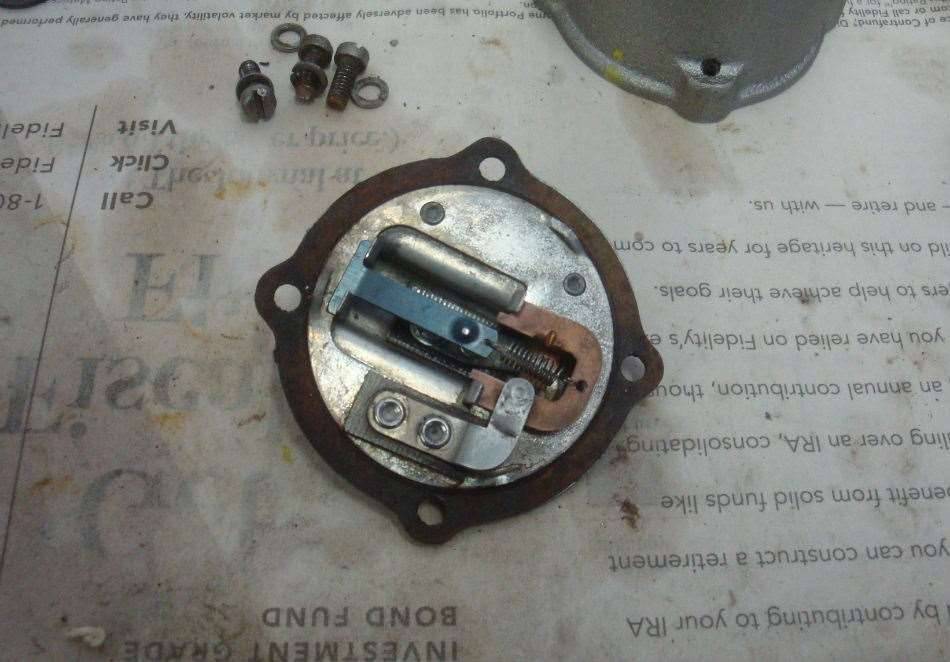 (58.48 KB) (58.48 KB)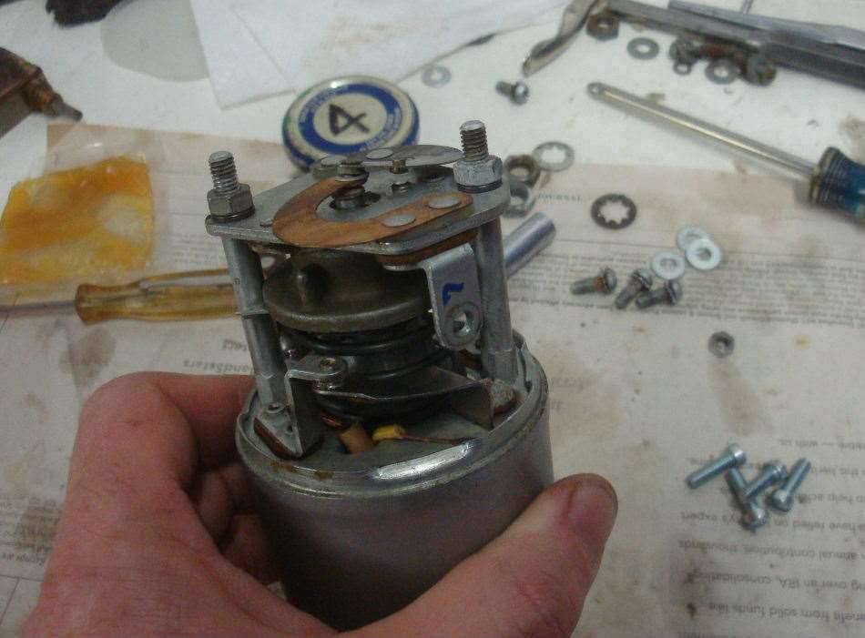
Posted on: 2013/11/5 1:05
|
|||
|
||||
|
Re: Jeff's 48 Custom 8 Victoria Project
|
||||
|---|---|---|---|---|
|
Home away from home
|
Tuesday turned out to be a pretty big day. The engine finally made it's way back into the Packard. Way behind schedule, but it still feels good. Luckily, getting approval to attend orientation for my new job has been a real slow process, giving me enough time to get things done before I have to leave for Little Rock, Arkansas.
It's been a while since I last did any work on the engine in the project blog. Manifold installation was straightforward, but would have been easier with a helper. I rebuilt the Carter WD-O carburetor and found that the fast idle linkage was missing. It had been converted to a manual choke, and the perpetrator of the crime chucked the linkage. Later on I was able to find a complete WD-O on ebay that I could steal the linkage from. Rebuilding the fuel pump turned out to be more challenging than expected. I didn't take much in notes back when I took it apart, since the rebuild kits that I saw advertised came with instructions. I decided to buy my kit from Max Merritt when I purchased some other items, and guess what? No instructions included. I was really surprised that I could find almost no info on the internet about rebuilding these things. I finally found a copy of an old Motor manual with a good picture and some basic instructions. I had planned to purchase a new fuel pump heat shield from Max Merritt, but they didn't have any in stock, and the employee who made them was on vacation at the time I called in my order. I had bought a used one for the 288/327 engine, but it was a bit too short for the 356. I decided to make one from scratch, and it turned out to be fairly easy to do. The distributor was reassembled and got a Petronix electronic ignition kit installed because the breaker point cam had significant wear on the lobes. The distributor is a Delco unit, but the service manual says it should be an Autolite, so it may have been replaced in the past.  ....I had to bend up a whole bunch more metal lines for oil, fuel, and vacuum..........Did I mention that I hate bending and flaring lines? ....I had to bend up a whole bunch more metal lines for oil, fuel, and vacuum..........Did I mention that I hate bending and flaring lines?As I was installing items on the front of the engine, I found that the generator has the wrong pulley on it. It's for a ?" wide belt instead of the 1" belt. I've been looking all over, but can't find the correct pulley anywhere. The Electromatic Clutch control unit went on next. The knucklehead that took the head off of the engine bent the linkage real bad, and it broke right at a cotter pin hole. Luckily, I was able to braze it back together. The unit will not be functional because it needs a new diaphragm in the big vacuum chamber, and that wasn't one of the priorities. I did notice that my linkage seems to differ a bit from what's in the parts book. The book shows an extra bracket off of the intake manifold for the throttle return spring. I don't have the bracket, and I don't think the spring would be at the right angle if I did have it. I put the return spring down on the linkage near the gas pedal. The last item to be installed on the engine was a new set of plug wires that I bought from Kanter. They are the shiny, lacquered wires with rubber boots on both ends. At first I wasn't impressed with them, but they turned out to be pretty nice. You have to fine tune them to length, but that means that you actually have wires that are the correct length when you are done, unlike most pre-assembled wire sets, in which the shortest wire is always too long and the longest wire is always too short. I'll find out soon if the wires will work with the Petronix ignition. It'll be a real shame if they don't. I've discovered one major issue with my nice new engine stand: the wide stance of the legs makes it impossible for me to get my engine hoist in position to lift an engine off of it. I have to pick off the engine with the forklift, set it down on the ground, then hook up the hoist. Once the engine was sitting on some wood blocks, I installed the oil galley and cam plugs, then the bellhousing and starter. I decided to leave the flywheel and clutch for after it was in the car, which I think turned out to be the right way to go. Lifting heavy engines makes me nervous. My hoist is US made, but as usual, the ram is from China. I've never had a ram fail, but I've had a bunch of the pumps go out over the years, which can make an engine drop pretty fast but not free-fall. I would have liked to take a photo with the engine sky high on the hoist to clear the top of the grill, but my nerves said "no, get that thing down to a lower altitude as quick as possible". The leveler really worked nice on this motor. You need to tilt it down at a fairly steep angle to get it in place, and then you can bring the back end up a bit, and the leveler lets you do that with ease. Once the front mount was touching the frame, I loosely installed the two bolts, and then I ran a chain across the rear to hold up the back of the engine. I'll leave the front bolts loose for now because I'll have to drop the back of the engine way down to get the trans in. November 5, 2013. Engine finally back in the car.....  Attach file: (91.00 KB)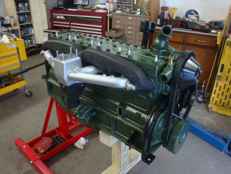 (88.00 KB) (88.00 KB) (86.31 KB) (86.31 KB) (75.74 KB) (75.74 KB)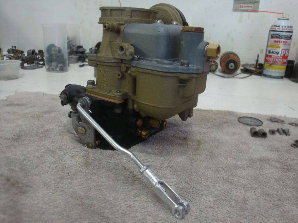 (73.89 KB) (73.89 KB)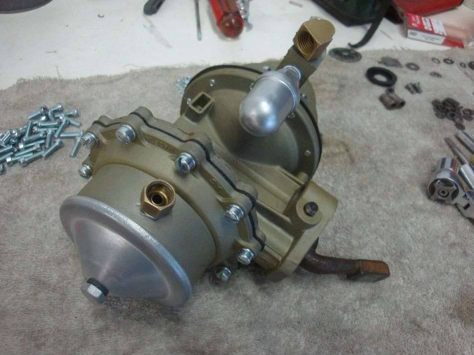 (59.80 KB) (59.80 KB) (92.13 KB) (92.13 KB)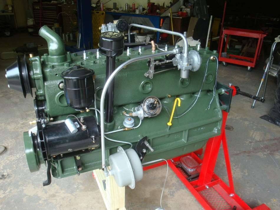 (57.39 KB) (57.39 KB)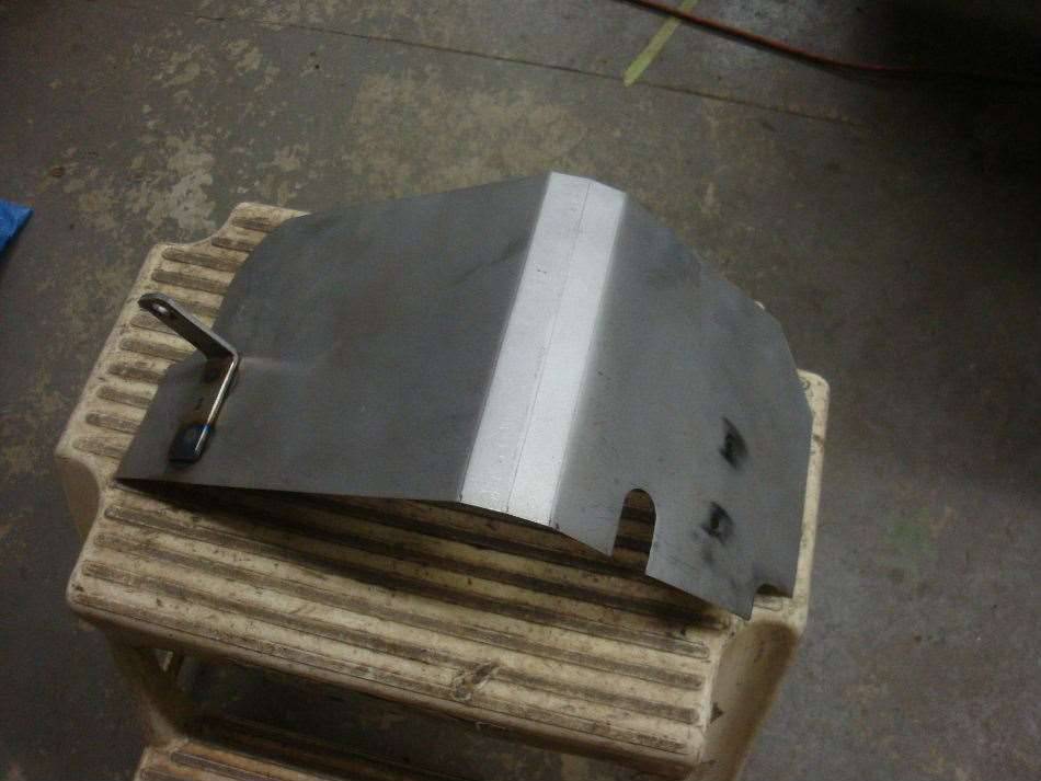 (58.20 KB) (58.20 KB) (76.21 KB) (76.21 KB)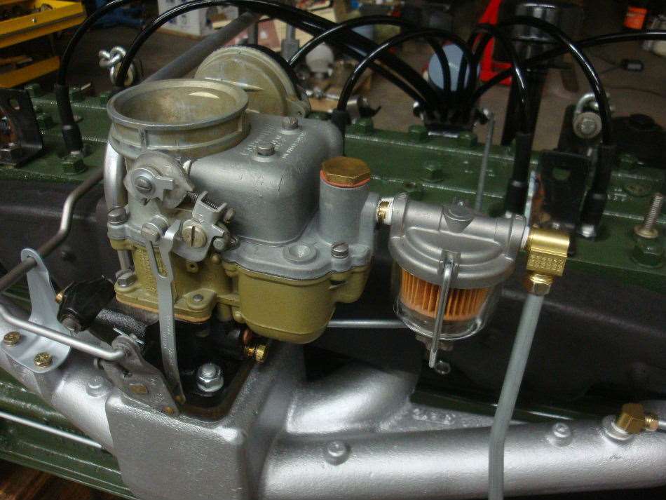 (67.30 KB) (67.30 KB)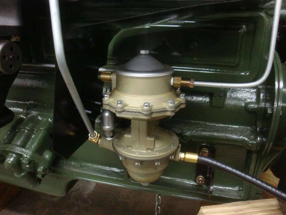 (94.10 KB) (94.10 KB)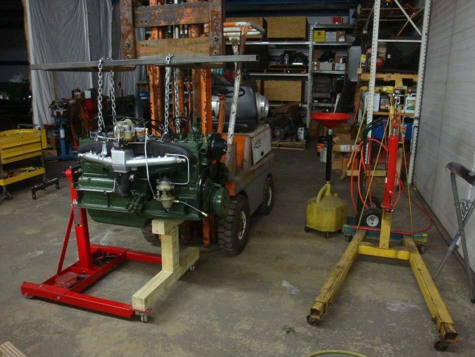 (79.75 KB) (79.75 KB) (84.92 KB) (84.92 KB) (88.43 KB) (88.43 KB)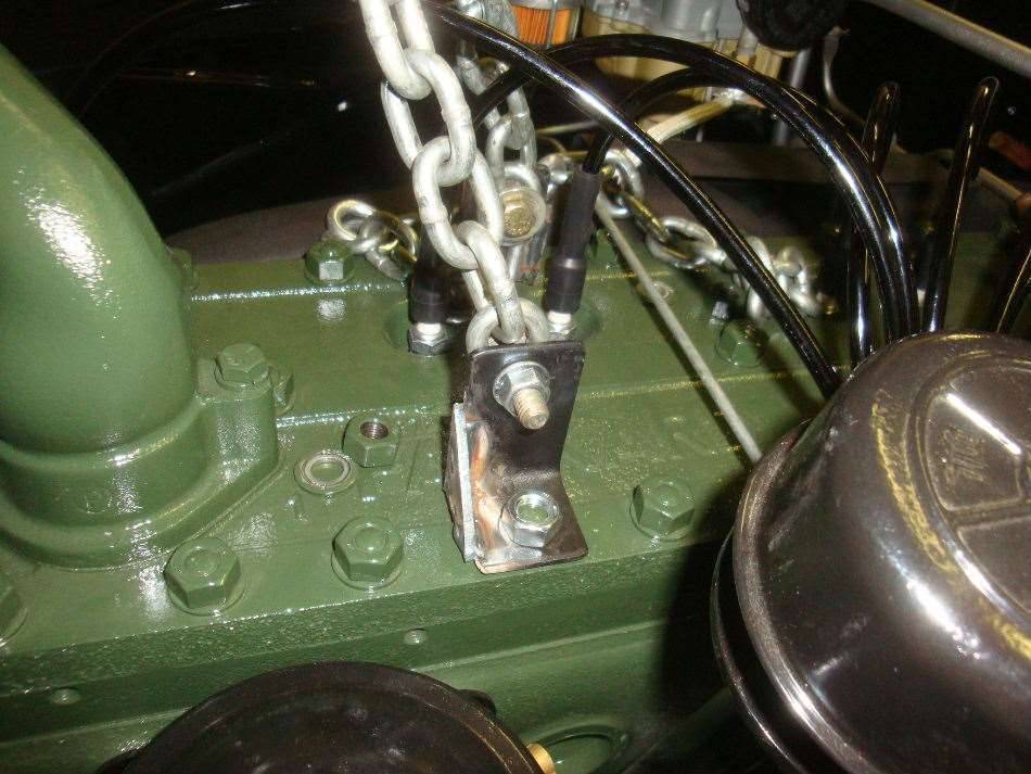 (65.03 KB) (65.03 KB) (65.22 KB) (65.22 KB) (87.19 KB) (87.19 KB)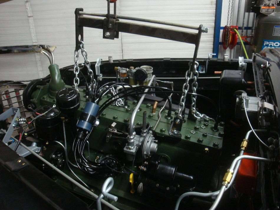 (104.54 KB) (104.54 KB)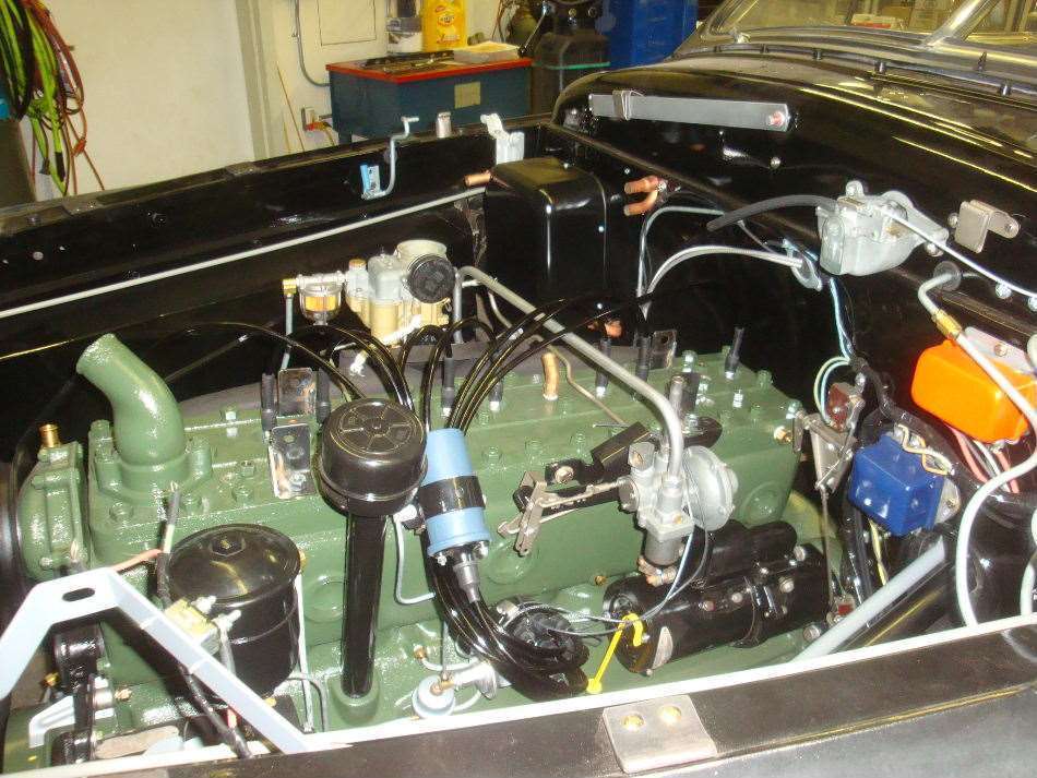 (104.55 KB) (104.55 KB)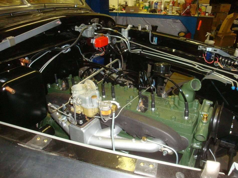 (87.16 KB) (87.16 KB)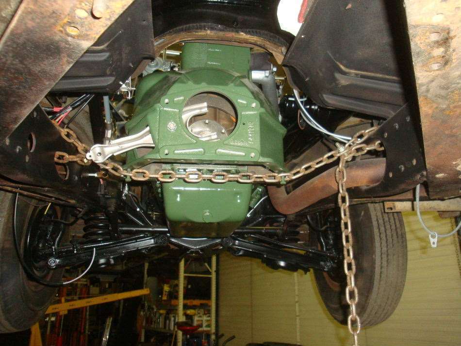
Posted on: 2013/11/7 2:21
|
|||
|
||||
|
Re: Jeff's 48 Custom 8 Victoria Project
|
||||
|---|---|---|---|---|
|
Forum Ambassador

|
Jeff, again let me congratulate you on the lovely workmanship. A comment - if you care about correctness it appears that you have the fuel section cover of the pump mounted 180 degrees from normal and that then affects the routing of the lines. Perhaps this image from the 22nd-54th series parts list best shows it.
Others may comment about the engine being green rather than gray so let me address that also. It's topic which has been very widely discussed on these pages and others without a 100% conclusive result. The overall assumption is that beginning with the 22nd series all engines were intended to be gray; I believe some club judging guides also indicate that though they may also have a disclaimer. I've never seen a 288 or 327 that was green and could lay a forceful argument to that being authentic. But there seems very little doubt that some very early 22nd series Custom 8s had green engines. My 22nd series Custom 8 sedan, car #124 and assembled in 1947, was very clearly green from the get-go and other examples have surfaced, also very early cars, that seem to also have a pretty solid case for early 22nd series 356 engines being green. The case is probably even stronger for 22nd series Custom 8 victorias as production for them began around the middle of 1947. Bob Neal's superb book on the 22nd/23rd series Packards may have more on this - I highly recommend this book to you if you don't already have it or have access to it. Attach file: (135.35 KB)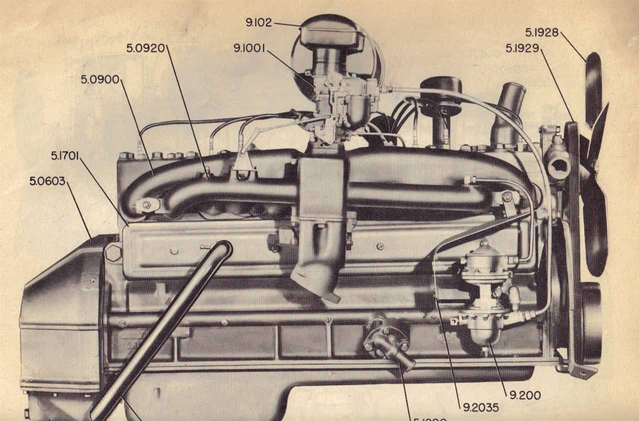
Posted on: 2013/11/7 11:24
|
|||
|
||||
|
Re: Jeff's 48 Custom 8 Victoria Project
|
||||
|---|---|---|---|---|
|
Home away from home
|
Thanks for the compliments and the suggestions. I will definitely check into the book. I had noticed the fuel pump discrepancy a while back when I was looking through the parts book. I was planning on posting a query about it, but came to the conclusion that Packard changed the fuel line routing somewhere along the way, or possibly the 356 was different from the smaller engines. For the setup that you posted the picture for, I think the fuel line on the frame terminates to the rear of the right side upper control arm. My fuel line terminates in front of the control arm. If I rotated the pump housing 180 degrees, the short rubber fuel line wouldn't reach. Maybe some other 22/23 owners will chime in on the subject to clear up the mystery?
Jeff Attach file: (80.10 KB)
Posted on: 2013/11/7 15:27
|
|||
|
||||
|
Re: Jeff's 48 Custom 8 Victoria Project
|
||||
|---|---|---|---|---|
|
Home away from home
|
Quote:
The parts book illustration is for the 288 and 327 engines and the 356 is different. The way yours is installed is correct.
Posted on: 2013/11/7 16:37
|
|||
|
||||
|
Re: Jeff's 48 Custom 8 Victoria Project
|
||||
|---|---|---|---|---|
|
Forum Ambassador
|
BDeB, thanks for that, you're right. I just took a look at the right-side engine illustration for the 356 engine in the 1948 Data Book and indeed, the fuel outlet is at the rear of the pump. There is a difference though, the fuel line inlet to the carb doesn't use an elbow but the line is in a gentle sweeping curve and enters the carburetor in-line. I stand corrected; it's a dull day when you don't learn something new and I'm going to have to take a closer look at my old 22nd series Custom 8.
Link to the data book with an excellent illustration of the pump and vacuum/fuel lines on a 22nd series 356. https://packardinfo.com/xoops/html/modules/article/view.article.php?99
Posted on: 2013/11/7 17:27
|
|||
|
||||
|
Re: Jeff's 48 Custom 8 Victoria Project
|
||||
|---|---|---|---|---|
|
Home away from home
|
I'm going to have to download that fact book. I suspect it has some good stuff in it. My original fuel line had a curve on it before going into the carb, but I decided to add the fuel filter and eliminate the curve. I have to say that many of the original metal lines were crudely bent, almost if they were done quickly by hand as the cars were going down the assembly line. Only the power accessory hydraulic lines and oil lines were neatly done. It's not often that I'm able to do a nicer job bending lines than the factory did, but this car is at least twenty years older than what I'm usually working on. Also, I'm probably being more careful on this car than on others that I have done.
Jeff
Posted on: 2013/11/8 10:00
|
|||
|
||||


