|
Re: '34 718 Std 8, 2/4 Coupe, Engine & Drive Train Diagram(s)
|
||||
|---|---|---|---|---|
|
Just can't stay away
|
That's a resource for which I've been likewise scouring the web, Tom, with similar results (for my 818).
The old publications you mention are great, but they omit an enormous amount of assumed knowledge. I'm gradually finding that my car's systems are not exactly as they were when they left the factory, having been modified by bush mechanics without access to genuine Packard parts and expertise. Idea: For each different chassis a web-accessible set of carefully made and labeled photographs of the original systems would be a highly valuable resource for those of us trying to preserve or restore one. Obviously it would require a lot of cooperation from custodians of original cars; would be an immense project to put such a resource together. Cheers, John
Posted on: 2016/5/21 2:35
|
|||
|
||||
|
Re: '34 718 Std 8, 2/4 Coupe, Engine & Drive Train Diagram(s)
|
||||
|---|---|---|---|---|
|
Forum Ambassador
|
Perhaps I assume too much and am surprised by your comments, there really is nothing about the engine and driveline that wouldn't be readily apparent and obvious to anyone in the auto trade, then and now - it's a very basic and simple layout differing only in very minor details from most all other makes of cars; in fact it differs very little from a 1954 Packard in concept and execution. The intake manifold is the one attached to the carburetor and air filter, the exhaust manifold is the one attached to the exhaust system. Water pump is up front, driven by twin fan belts. Perhaps the lest common feature on the '34 Eight is the oil cooler attached to the front end water jacket plate, just a simple heat exchanger, and a feature Packard continued on the senior cars thru 1939.
I've lived with a very original '34 Eight for 50+ years and would be glad to answer any specific questions.
Posted on: 2016/5/21 7:13
|
|||
|
||||
|
Re: '34 718 Std 8, 2/4 Coupe, Engine & Drive Train Diagram(s)
|
||||
|---|---|---|---|---|
|
Home away from home
|
O_D, I understand where John & Tom are coming from. I kinda run into that myself a few years ago but by reading a lot (which I don't mind) I self educated myself. Also by (trial and error sometimes) I fixed and repaired minor stuff slowly moving up to more difficult tasks.
Posted on: 2016/5/21 11:57
|
|||
|
I can explain it to you but I can't understand it for you
 Bad company corrupts good character! Farming: the art of losing money while working 100 hours a week to feed people who think you are trying to kill them |
||||
|
||||
|
Re: '34 718 Std 8, 2/4 Coupe, Engine & Drive Train Diagram(s)
|
||||
|---|---|---|---|---|
|
Home away from home
|
BDC & OD (and John), I thank you for your comments. I am a new Packard owner and the last time I seriously tried to work on a car was in the mid 1950's. So for example, I noticed what I determined was gas coming out of a brass tube hanging down from someplace next to the engine. I had no idea what I was looking at, why it was there or if it was even stock equipment. A source in the NorCal club took my call and after a fumbled explanation from me he figured out I was talking about the Carburetor Overflow Valve. Shortly after that I found a brief article in the 120 Shop Manual and mystery is solved. I know it all seems 2nd nature to you who have been Packard owners for many years and are probably very good mechanics as well, but as basic as that engine and the engine compartment might be, it starts out a bit intimidating or frustrating to us newbies, and for me, a simple diagram of what all is under the hood would be a great help.
There is an article in the Packard Service Letters abut the Oil Cooler Replacement per Technical Letter # 1950. I don't know where the Oil Cooler is, what it looks like and I can not find Technical Letter 1950 anyplace, yet by reading a few notes here and there it seems Packard was very serious about making the changes. Maybe mine was up-dated along the way, or not...I don't know, or know how to know. My windshield wipers don't work (of course) so I'm trying to follow the vacuum tubing back down to....? There must be a vacuum reservoir someplace but I have no idea what it would look like, where it might be, or where that vacuum tube(s?) comes out of the firewall. These are just some of the issues I'm trying to get a handle on, and without a basic map, I'm having a bit of a time making any progress. Any ideas ? Thanks, Tom
Posted on: 2016/5/21 13:34
|
|||
|
||||
|
Re: '34 718 Std 8, 2/4 Coupe, Engine & Drive Train Diagram(s)
|
||||
|---|---|---|---|---|
|
Forum Ambassador
|
The oil cooler on 34 Eights and Super Eights is a LARGE casting attached to the front of the water jacket plate (driver's side of the engine). Immediately beneath it is the Purolator L-6 full-flow oil filter. Oil flows thru the core in one direction, water from the cooling system in the other to keep the oil warm in very cold weather, and cooler in very warm conditions.
The '34 oil cooler was problematic and with the availability of multi-viscosity oils a few years later, isn't an essential part of your engine though the oil flow much be keep intact. Some folks have removed the cooler completely, reverting to a 1933 configuration. Others like myself have kept it externally correct but replace the core inside with a shunt tube. 1935 thru 39 oil coolers were a very different design and quite trouble-free. To find it just follow the lower radiator hose. There is no reservoir for the wipers, instead they get supplied by vacuum at times of hard acceleration via the vacuum pump section of the fuel pump. The vacuum lines are very easy to follow, start with the primary take-off on the intake manifold (near the automatic choke) and just follow the lines - it will branch to the booster pump, the power brake cylinder under the seat, the power brake adjust valve on the cowl, the Bijur oiler (glass jar), and the wipers. Attach file:  (255.72 KB) (255.72 KB)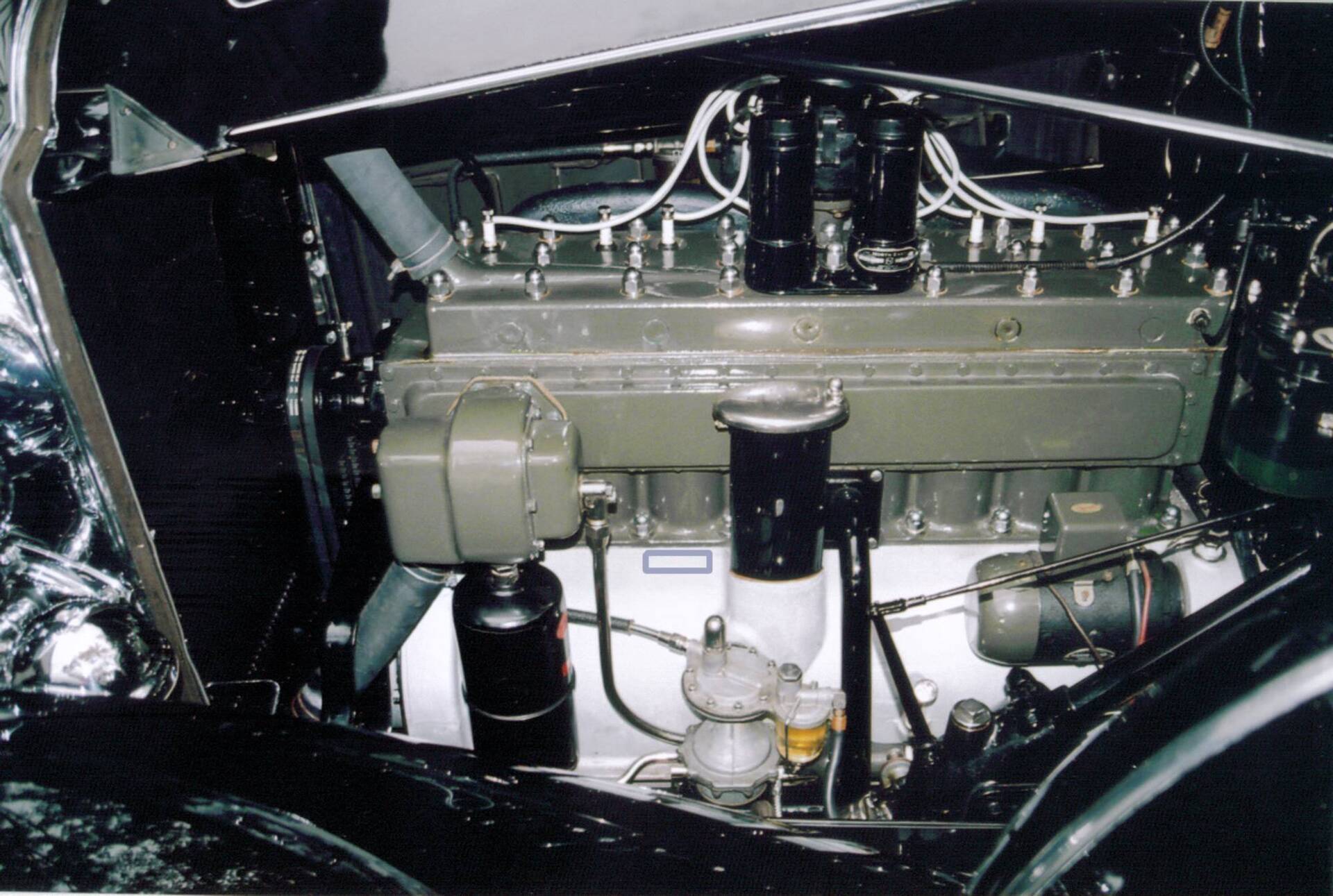
Posted on: 2016/5/21 14:59
|
|||
|
||||
|
Re: '34 718 Std 8, 2/4 Coupe, Engine & Drive Train Diagram(s)
|
||||
|---|---|---|---|---|
|
Home away from home
|
Thank you OD ! That information helps immensely and I appreciate it.
One more question for now if I may...aft of the oil cooler, down towards the bottom middle/rear of the engine there is a sort of tubular housing with brass lines connecting fore and aft of it and what looks like an inspection nut on top. The oil dip stick in almost on top of it and the breather tube passes over it. Can you tell me what this piece is(pump ?)and where the tubing/lines go ? I can/will follow them of course, but knowing in advance what I'm look at or for, will help. Thank you again. Tom Attach file: (184.56 KB)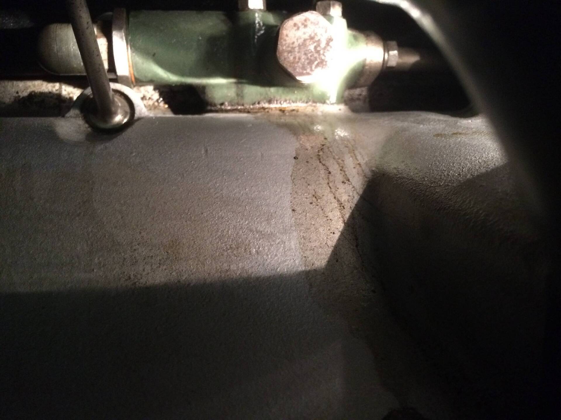
Posted on: 2016/5/21 16:13
|
|||
|
||||
|
Re: '34 718 Std 8, 2/4 Coupe, Engine & Drive Train Diagram(s)
|
||||
|---|---|---|---|---|
|
Forum Ambassador
|
That unit is the oil pressure relief valve, actually 2 valves. The adjustment screw under the acorn nut adjusts the maximum main oil pressure to a "not to exceed" pressure, 55 or 60 psi is the correct adjustment. The 2nd valve (under the hex cap) is unadjustable and will function to allow normal engine lubrication in the event the filter should clog. The two lines you see are from the pump outlet thru the relief valve to the filter, then thru the cooler and return from the cooler back the engine's internal main oil gallery.
Quite unique for the time and first appearing on Packard in 1934 is this "full flow" oil system, meaning that 100% of the oil that leaves the oil pump is filtered before reaching the engine internals. Packard retained this system on the 320 and 385 cubic inch Eights and Super Eights and Twelve engines thru 1939 but thereafter returned to simplier "bypass" filter systems, meaning only a portion of the oil leaving the pump is passed thru the filter. In modern engines of today full-flow filtration is the norm. Nothing uncommon in any of this, though in later engines of the postwar era and newer the pressure relief valve is normally inside the oil pan and not accessible.
Posted on: 2016/5/21 17:35
|
|||
|
||||
|
Re: '34 718 Std 8, 2/4 Coupe, Engine & Drive Train Diagram(s)
|
||||
|---|---|---|---|---|
|
Home away from home
|
Thank you very much O.D.,
I appreciate ALL the information especially the "why's and wherefore's" as that helps immensely in my education. All the Best, Tom
Posted on: 2016/5/21 18:07
|
|||
|
||||
|
Re: '34 718 Std 8, 2/4 Coupe, Engine & Drive Train Diagram(s)
|
||||
|---|---|---|---|---|
|
Home away from home
|
Tom, I read pretty much all the posts on prewar forum just to "educate" myself.
Posted on: 2016/5/21 18:40
|
|||
|
I can explain it to you but I can't understand it for you
Bad company corrupts good character! Farming: the art of losing money while working 100 hours a week to feed people who think you are trying to kill them |
||||
|
||||


