|
Re: DIY Torsion level control switch conversion
|
||||
|---|---|---|---|---|
|
Home away from home
|
H.
I ordered a pair. To check them out.. Might have to send to you. For examination.
Posted on: 2023/4/27 17:27
|
|||
|
Riki
|
||||
|
||||
|
Re: DIY Torsion level control switch conversion
|
||||
|---|---|---|---|---|
|
Home away from home
|
When they get Here
Will see what they are doing. And why.. Should be able to rearrange . things
Posted on: 2023/4/27 23:27
|
|||
|
Riki
|
||||
|
||||
|
Re: DIY Torsion level control switch conversion
|
||||
|---|---|---|---|---|
|
Home away from home
|
H.
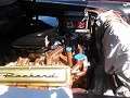
Here it is. Un solder 30?. And move to another terminal? Attach file:  20230429_161215_(1).jpg (342.97 KB) 20230429_161215_(1).jpg (342.97 KB)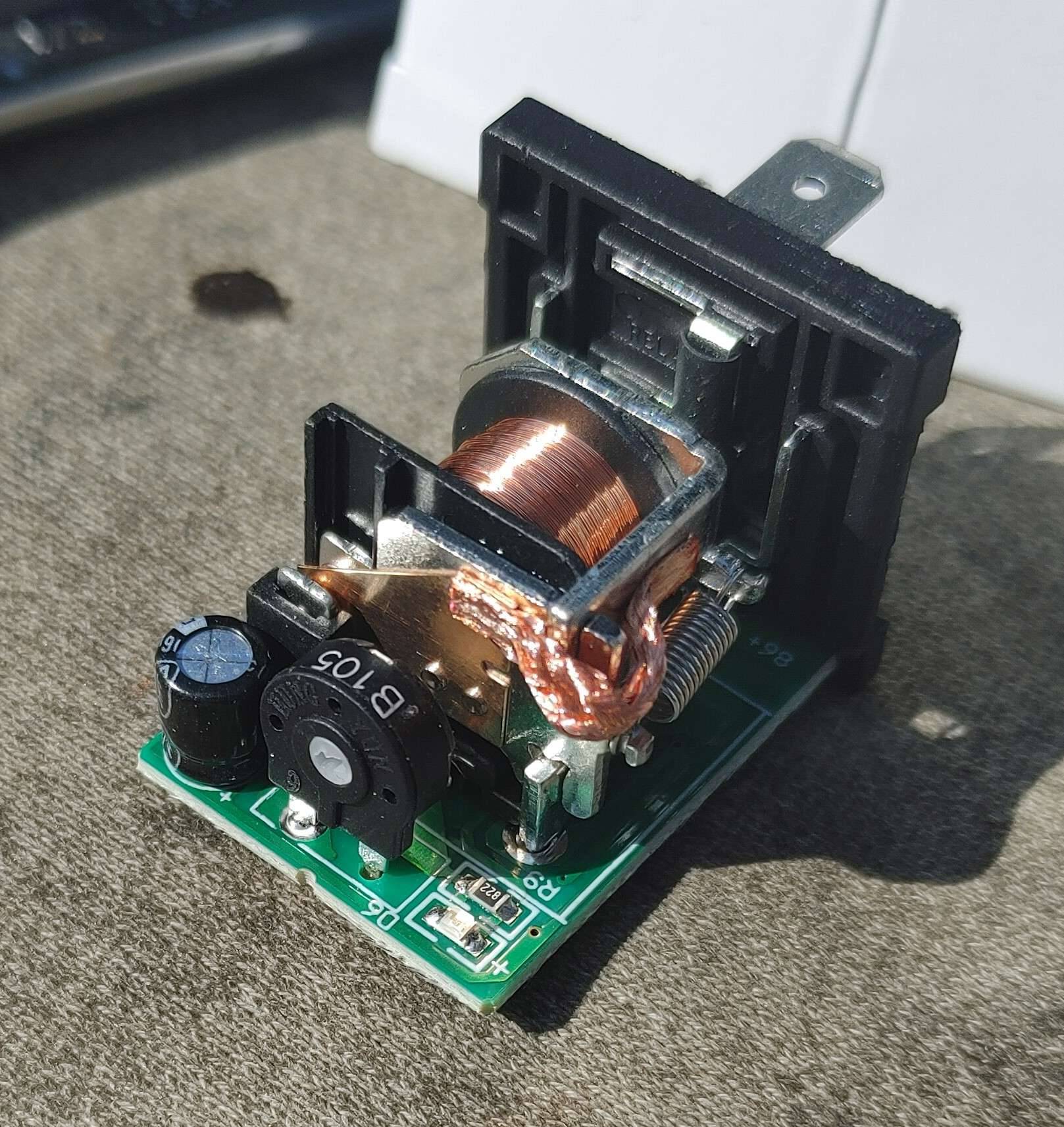 20230429_161304_HDR_(1).jpg (250.85 KB) 20230429_161304_HDR_(1).jpg (250.85 KB)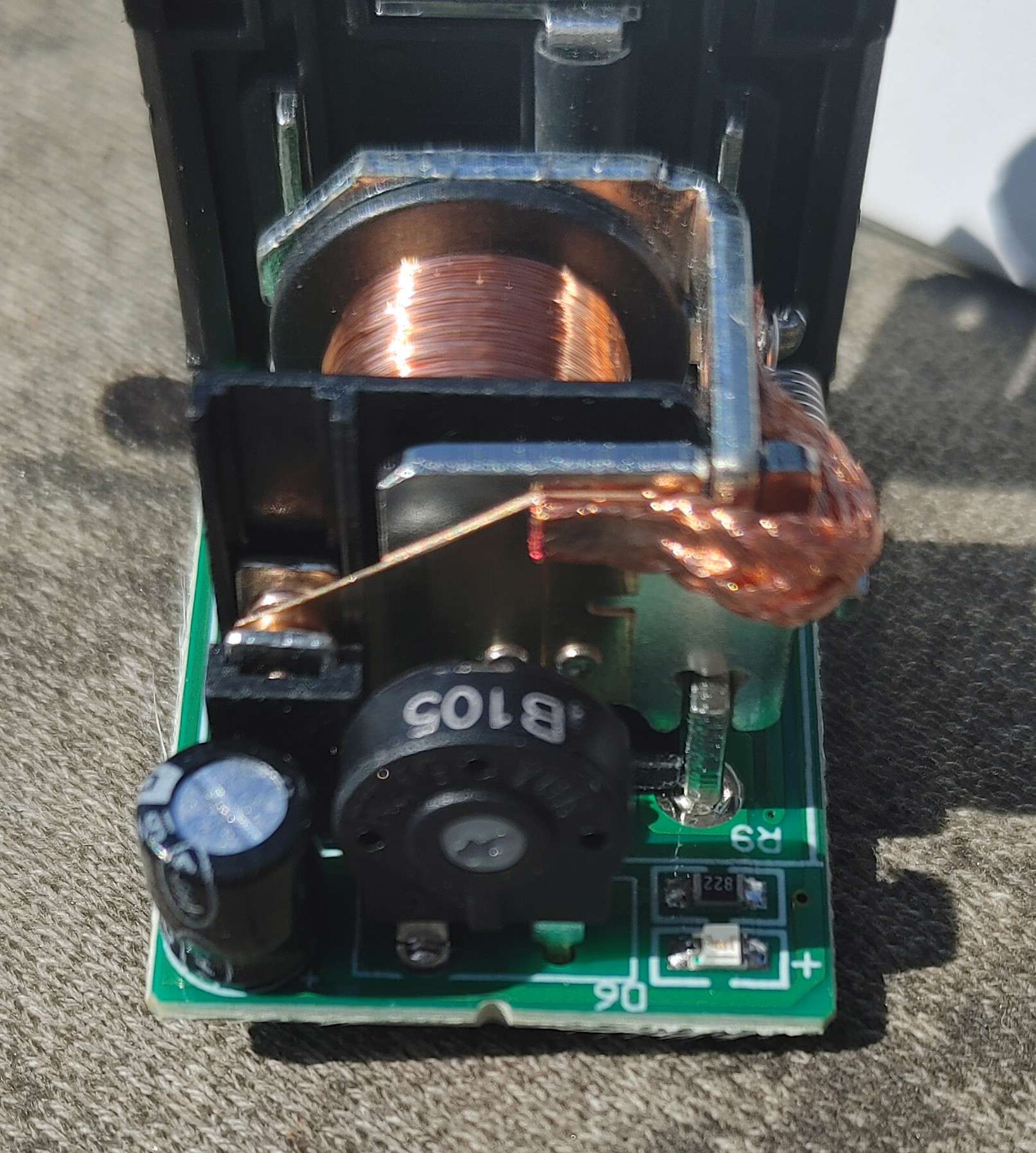 20230429_161428_HDR_(1).jpg (219.11 KB) 20230429_161428_HDR_(1).jpg (219.11 KB)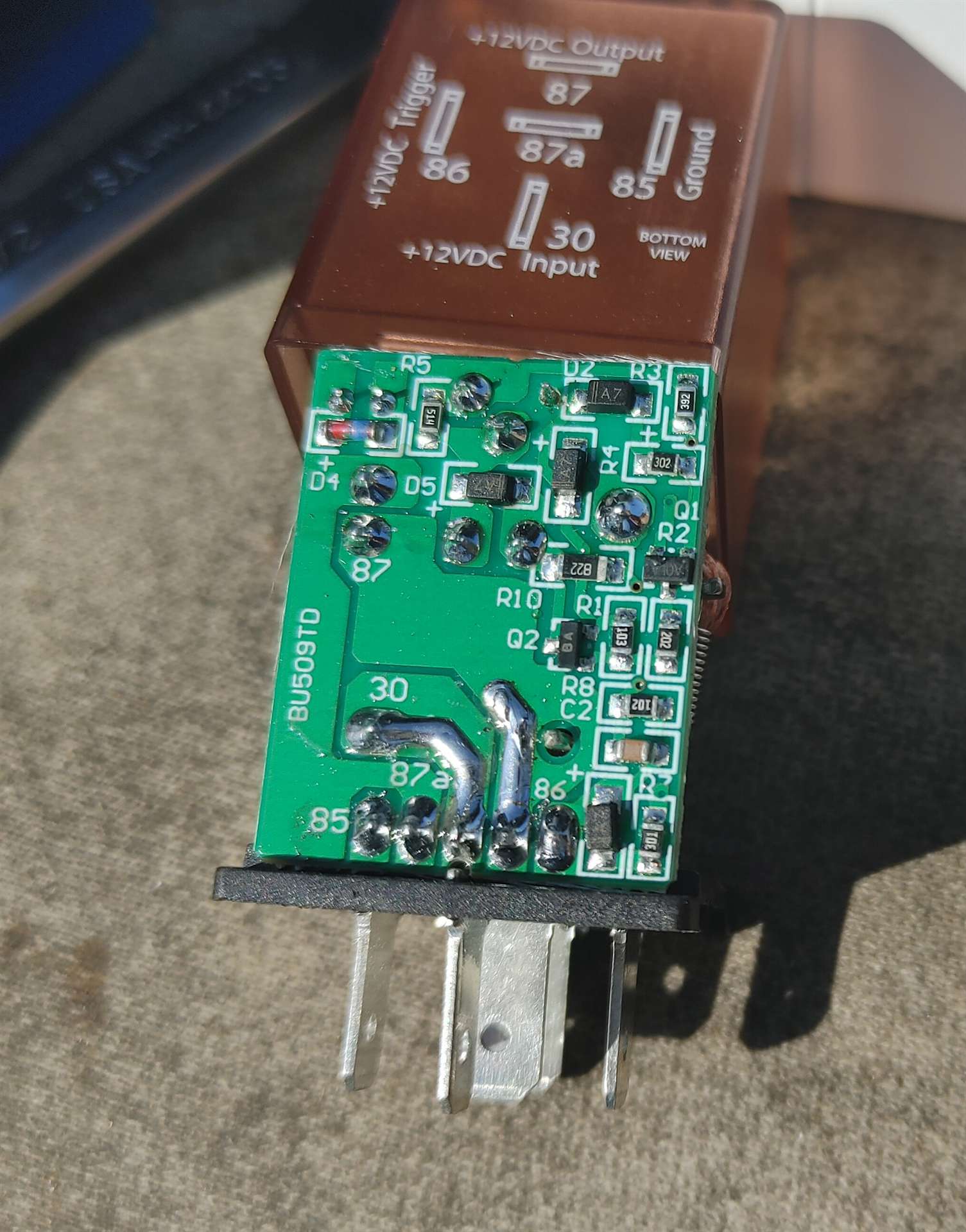
Posted on: 2023/4/29 19:53
|
|||
|
Riki
|
||||
|
||||
|
Re: DIY Torsion level control switch conversion
|
||||
|---|---|---|---|---|
|
Forum Ambassador

|
Try the relay without 30 connected using only 85 and 86 and see if it even pulls in. If it does not then need to see where 30 goes and what else it feeds on the board. It will definitely go to the relay contact common but the way the statement reads it is probably feeding power to the electronics somewhere else on the board. If it is hopefully it is only in one place.
Depending on how many other places it goes 30 MIGHT be able to be isolated from the electronics and feed only the relay common. The electronics may be able to be powered simultaneously by the same 12v at the trigger pin. Without a schematic it is hard to say and trying might ruin the relay.
Posted on: 2023/4/29 20:34
|
|||
|
Howard
|
||||
|
||||
|
Re: DIY Torsion level control switch conversion
|
||||
|---|---|---|---|---|
|
Home away from home
|
H.
30 is that dark area. Only . don't see anything connected . So they must be using that leg of relay for positive. Attach file: image_2023-04-29_21-46.jpg (54.82 KB)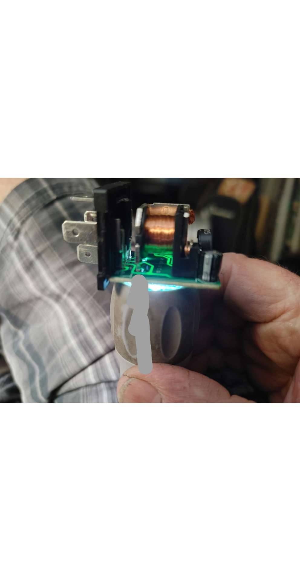
Posted on: 2023/4/29 23:49
|
|||
|
Riki
|
||||
|
||||
|
Re: DIY Torsion level control switch conversion
|
||||
|---|---|---|---|---|
|
Home away from home
|
Putting power on 86.
Trigger to 30. Relay stays pulled in till power is removed from 86. Triggering from 86 to 30 starts timing. The adjustable resistor could be better. I can get 5 seconds. Of coarse a fixed resistor can be used. EDIT. timing starts after power 86. Is removed from 30. Attach file: 20230430_151033.jpg (291.95 KB)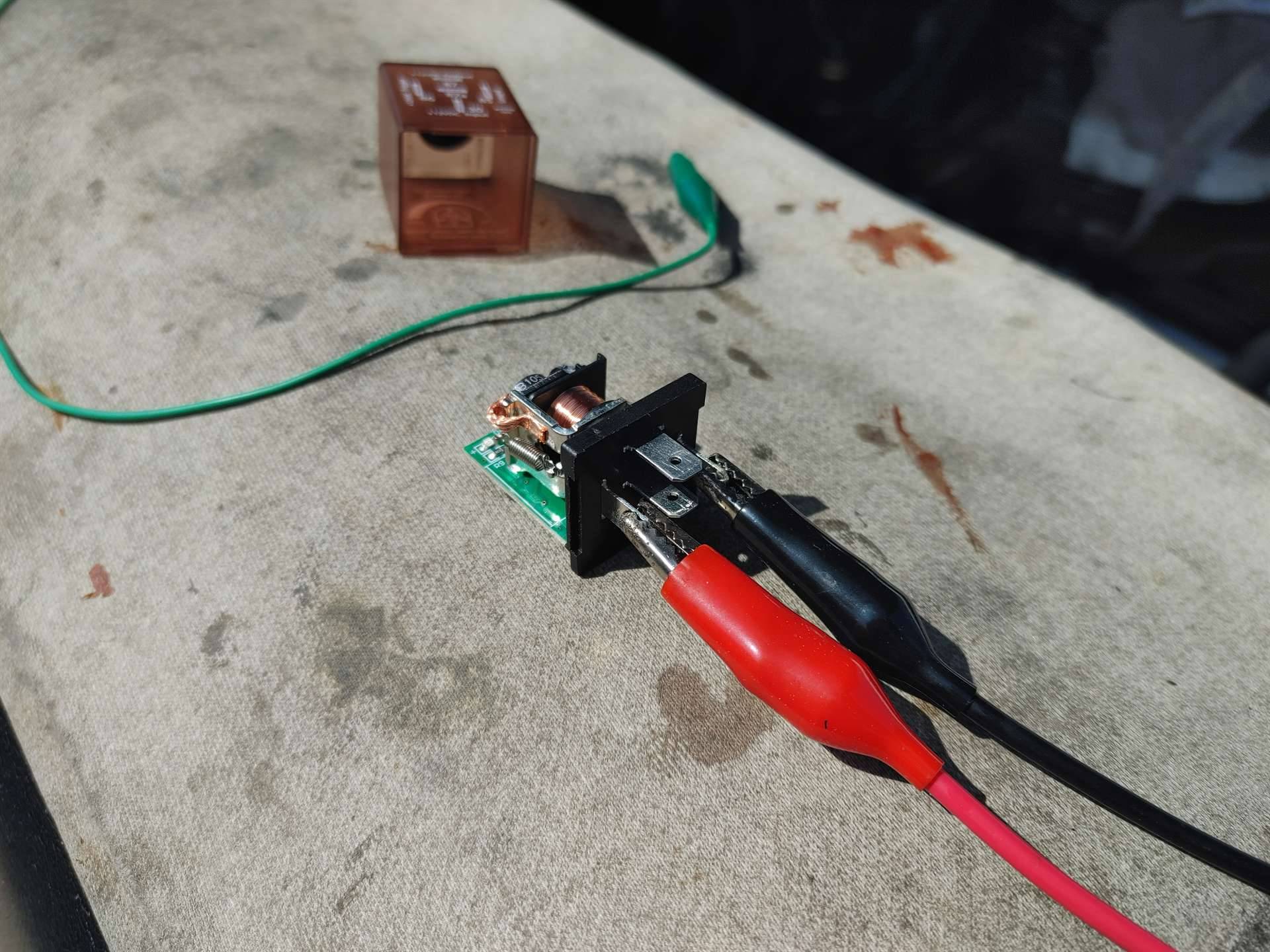 20230430_151246.jpg (341.39 KB) 20230430_151246.jpg (341.39 KB)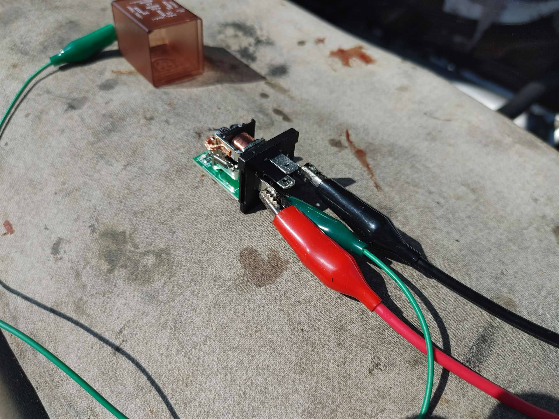
Posted on: 2023/4/30 17:42
|
|||
|
Riki
|
||||
|
||||
|
Re: DIY Torsion level control switch conversion
|
||||
|---|---|---|---|---|
|
Forum Ambassador
|
In other words 30 does need power for it to work. Unless you want to chance damaging the relay by trying to separate 30 from the electronics it will not work on a stock layout with solenoids.
It might be possible to use it to do the direct power but the current capability of the N.O. contact is at what I consider a minimum. I have no idea what the contact arcing would be like when it closed or worse, opened to cut the motor off. If that is substantial it could overheat or even weld the contacts. Arcing could be the reason they used solenoids instead of relays in the first place. If trying direct power, I would also change the 56 fuse layout to have the 7 1/2 amp feed the brake circuit directly from the power wire instead of first going thru the 30 amp fuse. Change the 30 to a 20 like the 55s used and wire that fuse to only protect the motor. With fuse changes and a bracket or sockets the relays could mount where the existing solenoids are located.
Posted on: 2023/4/30 18:15
|
|||
|
Howard
|
||||
|
||||
|
Re: DIY Torsion level control switch conversion
|
||||
|---|---|---|---|---|
|
Home away from home
|
30 can be de soldered.
Its the metal case of the relays Then cut foil so relay is isolated. EDIT one thing I'm not sure about is start timer. Cause it only need to be momentary power
Posted on: 2023/4/30 20:10
|
|||
|
Riki
|
||||
|
||||
|
Re: DIY Torsion level control switch conversion
|
||||
|---|---|---|---|---|
|
Forum Ambassador
|
Yes but whatever circuitry 30 is powering will still need to come from somewhere. It will need to be isolated and be sure no other connection to 30 is hidden somewhere. 30 would need to be a ground and only connecting to the contact common for relay to work with the stock system.
Maybe whatever else 30 powers could come from 86 at the same time as the trigger signal but if not, then need to figure a way to power the electronics. That could probably be done by adding a small wire to power the electronics and connect it to the light green terminal on the switch box. The pivot contact would still work the trigger at 86 to start the timing.
Posted on: 2023/4/30 20:30
|
|||
|
Howard
|
||||
|
||||


