|
Re: Owen Dyneto generator wiring
|
||||
|---|---|---|---|---|
|
Forum Ambassador

|
The Franklin schematic on the ebay offering doesn't show a fuse but does show the grounded field and third brush just as your generator is configured. It is an interesting arrangement with the armature and the way the brushes are positioned supplying two separate closed voltage loops to individual pairs of field coils.
It appears it would rely on residual magnetism in order to supply a small starting voltage to energize the fields which in turn would enable more and more output as the fields strengthen until output reaches a maximum. I's like to find a description on how the regulation is done but I am guessing it is in the winding of the coils which reach a point where the strength reaches a max. I know it is just an illustration but it almost looks like the coil pairs are counter wound. If so there may be a point the field pairs will start to oppose each other so output cannot exceed a threshold. Do the third brush generators get polarized the same way the more modern units do? That might be something to think about on yours. If there is no residual magnetism to start an output I don't see how there could ever be enough voltage supplied to the field to provide any kind of decent output.
Posted on: 2017/11/24 16:41
|
|||
|
Howard
|
||||
|
||||
|
Re: Owen Dyneto generator wiring
|
||||
|---|---|---|---|---|
|
Home away from home

|
Wow, that wiring diagram puts another wrinkle in the mystery! The circuitry is nothing like any other diagrams or descriptions I've seen for third brush generators.
So the Franklin generator has two separate fields providing current at either 2 amps or 75 amps. 75 amps is way too much current, and 2 way to little. Do the two fields offset each other somehow to provide the 8 to 14 amps needed depending upon load? I have had it suggested to me that polarization is indeed sometimes necessary on these old third brush generators. If it has been sitting unused for a long time, the residual magnetism fades away to nothing. I was told to touch a lead from the negative post of the battery to the generator lead that supplies current to cut-out very briefly a few times and that would do it. I did try that but no dice. I've read you can polarize them backwards. Maybe I did that, or maybe with this novel circuitry, you have to go about it another way. Measured resistances as best I could trying to ascertain whether the wiring is still good within. With both leads disconnected from the grounding post next to the third brush (i.e. the lead from third brush and the lead from at least one pair of field coils are disconnected - the other pair of field coils may be grounded elsewhere), if I ground one wire from the ohmmeter and touch the other to any of the brushes, I get 12 ohms resistance. Connect one wire to the (disconnected) lead that goes to the cut-out, I get 2 or 3 ohms resistance at each brush. Does this make sense given the wiring configuration in the diagram? Attach file:  (279.66 KB) (279.66 KB)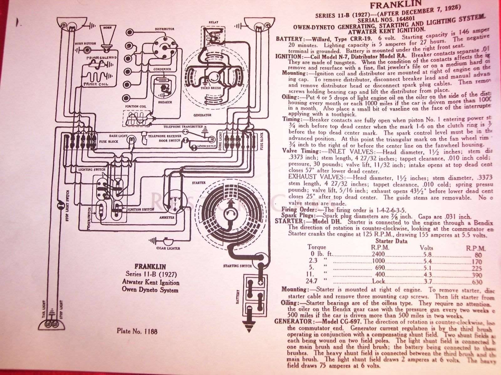
Posted on: 2017/11/24 17:14
|
|||
|
Rob
1930 Custom 8 Club Sedan |
||||
|
||||
|
Re: Owen Dyneto generator wiring
|
||||
|---|---|---|---|---|
|
Home away from home
|
Apparently, the Franklin generator is compound wound. Instead of having all four coils simply shunt wound (in parallel with the armature) like most, the two coils of the "light" shunt field are parallel wound while those of the "heavy" shunt field are series wound. One set compensates the other under variable loads and voltage remains constant. This eliminates the need for a voltage regulator or fuse.
Attach file:  (9.28 KB) (9.28 KB)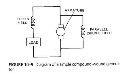 (29.24 KB) (29.24 KB)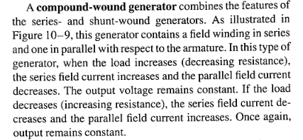
Posted on: 2017/11/24 19:16
|
|||
|
Rob
1930 Custom 8 Club Sedan |
||||
|
||||
|
Re: Owen Dyneto generator wiring
|
||||
|---|---|---|---|---|
|
Home away from home
|
[by HH56 on 2017/11/24 17:53:36
The Franklin generator must add another wrinkle to the series/parallel winding. Looking at the schematic, the parallel shunt winding is plain. Out the top right brush thru the field coils and to ground at the ground connection. I would really like to see a more generator specific writeup and better quality schematic of the generator to see if that is a solid ground connection at the third brush or is it a bleed over from the fuzzy print. If it is a solid ground connection then I am not understanding the circuit and how they get the series portion of the field connected as part of the output. The grounded third bush seems incompatible with it being a series winding because if it is grounded it would not seem to be a series arrangement anymore. It would appear to me it is a second but heavy parallel winding because the series aspect would be short circuited at the grounded brush and not be in series with the output. If there is no grounded third brush then it would definitely be a series -- out the bottom right, thru the fields, back in the third brush and thru an armature winding and out. With the brush grounded I can't see any output other than that developed between the grounded brush and a few armature windings to the top right output brush. If anyone has the knowledge or an old auto electric manual that explains this particular generator I could sure use some enlightenment.] Howard, I see your point. The "heavy" series windings wouldn't connect with the load if there is a grounded third brush. Maybe the wiring diagram omitted the little "hump" that would indicate no connection between the third brush to heavy shunt field lead and the light shunt field to ground lead. If the third brush and heavy field leads were simply connected to each other and not grounded, the series circuit would operate as you describe. The "light" shunt field could well be grounded at another spot on the generator body. My resistance tests between brushes and the generator case, with the two leads in question disconnected, suggest there is another wire grounded somewhere else to the case. That would comport with your analysis.
Posted on: 2017/11/24 20:41
|
|||
|
Rob
1930 Custom 8 Club Sedan |
||||
|
||||
|
Re: Owen Dyneto generator wiring
|
||||
|---|---|---|---|---|
|
Forum Ambassador
|
I would still like to see a better quality schematic to be sure the third brush is grounded but assuming it is, I may have figured it out. If so I need to rethink the direction of flow.
The explanation will probably get scrambled in the typing and I could still be all wet but if my understanding is correct, the grounded third brush is the 0 point of both the armature and field coils. The other two brushes provide the connections to complete the series arrangement as well as provide the output. Because of the way two or more armature windings connect to a single commutator segment the series portion utilizes windings in the armature to complete the series circuit. The shunt coil takes the output voltage and goes directly to ground for the parallel portion. The third brush moves to change the relationship of how far away a particular commutator bar and its connected armature windings and poles might be from a field shoe before it connects and disconnects -- effectively subtracting or adding armature windings to the total to control the max output. Farther away and a lower magnetic strength gives a lower output, nearer is higher. Anyway, until I can read a professional explanation that is my current theory.
Posted on: 2017/11/24 21:13
|
|||
|
Howard
|
||||
|
||||
|
Re: Owen Dyneto generator wiring
|
||||
|---|---|---|---|---|
|
Home away from home
|
Howard, Your explanation makes sense, not that I would've intuited it. I'm not too clear on how the armature works.
If so I need to rethink the direction of flow. Doesn't the direction of current flow determine how you polarize the generator? How would you polarize if the grounded third brush is the 0 point of both armature and field coils?
Posted on: 2017/11/24 22:47
|
|||
|
Rob
1930 Custom 8 Club Sedan |
||||
|
||||
|
Re: Owen Dyneto generator wiring
|
||||
|---|---|---|---|---|
|
Forum Ambassador
|
"Direction of flow" was a bad choice of words on my part. I was thinking more about the wiring and flow path thru the armature rather than conventional positive or negative current flow.
The polarizing process would not be affected because it relies on the internal wiring of the generator to orient the field shoes in the proper relationship to the armature poles. As soon as the polarizing connection is made the heavy current surge thru the field coils connecting back to ground will cause the shoes to turn into a brief electromagnet. The respective north or south poles are established depending on whether it was a positive or negative going surge. On a modern generator the process is simple -- the input current goes thru the field coils and then via the closed regulator contacts back to ground establishing the electromagnets. While your particular generator has the direct field connections between the terminal and ground needed I confess to not knowing enough pure theory to understand how the same process can be done on a generator with a fuse in the field coil circuit without blowing the fuse. Hence the earlier question on if or how polarizing was done on those generators.
Posted on: 2017/11/25 11:14
|
|||
|
Howard
|
||||
|
||||
|
Re: Owen Dyneto generator wiring
|
||||
|---|---|---|---|---|
|
Home away from home

|
Not sure if i can help but keep in mind that ANY mechanical generator is a TWO stage generator.
In that the INTITIAL formation of electric current is AC (alternating) current. It is the sole purpose of the commutator to transform the AC into DC current.
Posted on: 2017/11/25 12:49
|
|||
|
VAPOR LOCK demystified: See paragraph SEVEN of PMCC documentaion as listed in post #11 of the following thread:f
https://packardinfo.com/xoops/html/modules/newbb/viewtopic.php?topic_id=7245 |
||||
|
||||
|
Re: Owen Dyneto generator wiring
|
||||
|---|---|---|---|---|
|
Home away from home
|
So the current alternates its flow direction in the armature. How does the commutator turn that to DC?
The Franklin compound-wound generator has no fuse, so no issue there. I already did the process of re-magnetizing the shoes, so will next try turning up the field(s) by moving the third brush counterclockwise.
Posted on: 2017/11/25 14:34
|
|||
|
Rob
1930 Custom 8 Club Sedan |
||||
|
||||


