|
Re: Temp sending Unit
|
||||
|---|---|---|---|---|
|
Home away from home

|
With key on and old sender hooked up, gauge is at H rest, then gauge gets power (actually, it always has power, thanks to previous person's wiring, had to play with that.) it goes right down to C. Hook up other sender, goes right to H. Didn't even put it in the water, no need to see it won't work.
I did come across another solution that may work, but not look the best and read a bit low. If i install an elbow in the sender port pointing horizontally along the block, then an adapter up to the thread size of the early sender, then about 2-3 inches of pipe, then finally the sender and a male to mail pipe adapter, it should read decently. I would think though, that with the probe out of the current "flow", that the coolant in the "sample tube" I've created might cool slightly and not move out of that area, creating a cooler "pocket", and the air around the engine might cool the pipe down slightly. I could use an adapter, then pipe, then male to male adapter and the sender, but then it'd stick out a mile into the engine bay. Might be a more accurate reading though. I REALLY don't want to drill and tap it with the motor in, there's not a straight shot at the hole. This might be the best and cheapest compromise. Thank everyone for the info, links, and brain power! One more thing to consider when swapping a newer motor into an older chassis. (Also, had to drill and tap throttle crosshaft holes, the newer head did not have them in that spot.)
Posted on: 2011/1/24 20:08
|
|||
|
||||
|
Re: Temp sending Unit
|
||||
|---|---|---|---|---|
|
Forum Ambassador

|
After re reading the gauge electrical description, I was afraid that would happen. Other than trying a GM sender which probably won't work either, the plumbing might be the best, quickest and ultimately cheapest option.
Instead of the elbow and long pipe with no circulation, what about something like this which will be shorter and might get more action. I threw in a baffle and if I remember the water circulation diagram, if pointed toward the rear of block it should grab a bit of flow and feed it in. Of course, it may not be necessary and maybe not worth the effort to braze or solder it in. Not sure how long the sender is either so maybe a little more tee length would be needed. A nipple and cap could be there instead of plug. I would use brass if you tried the baffle but galvanized would probably work as well without. Anyway, just a thought Attach file:  (16.66 KB) (16.66 KB)
Posted on: 2011/1/24 20:50
|
|||
|
Howard
|
||||
|
||||
|
Re: Temp sending Unit
|
||||
|---|---|---|---|---|
|
Home away from home

|
Can you adapt a 51-53 gauge to your cluster? I'm not too familiar with the '50 dash, but maybe the shape of the gauge in the back of the cluster is similar? My '51 gauge is round even though it shows through a slit in the front.
Posted on: 2011/1/24 22:31
|
|||
|
[url=h
|
||||
|
||||
|
Re: Temp sending Unit
|
||||
|---|---|---|---|---|
|
Home away from home
|
I would rather not have to tear into the dash, it's such a pain and probably a last resort. I'd honestly probably put a new gauge that comes with its own sending unit in the glove box first before messing with the dash. I'd probably put a volt meter and a tranny fluid temp gauge in there as well if i was going to add some things i want to keep an eye on.
HH56, That seems like a cleaner design. I'm sure with effort and your baffle idea we could actually make a flow path, but i'm confident it would read closely just being in there. Thinking about it, even if the coolant wasn't flowing through, just being in contact with the hot rushing coolant should keep the temp up. I think this is probably the best option, and pieces could be had at home depot instead of heading to the parts store and having the kid ask me what's it fit.
Posted on: 2011/1/25 0:34
|
|||
|
||||
|
Re: Temp sending Unit
|
||||
|---|---|---|---|---|
|
Home away from home
|
Built what we showed up above with 1/4 and 3/8 pipe parts (too tight for baffle). Had to drill the plug open a little more too so it wouldn't bump into the sender's probe, which is just shy of the length of the T. I like the plug at the end because you can bleed it to be sure that there's no air pocket there.
Put it all together and found that it just barely hits the throttle linkage, even if everything was as tight as can be. Thinking now i'll try a 1/4" street l, adapter to 3/8, then small length of 3/8 pipe along the block and finally coupler with sender in it. Should stay tight enough to the block to not interfere with throttle linkage. After the block warms up and the steel pipe get's as hot as the block, i think that it couldn't be more than a few degrees off from the water rushing right by there, 10 degrees max? We'll see when it's running. Maybe get it hot, see what the gauge says, then take the plug out and let some antifreeze out and measure the temp? I'm sure there's a smarter way but i'm tied up on other details and haven't sorted out how to tell if it's accurate yet.
Posted on: 2011/1/29 14:02
|
|||
|
||||
|
Re: Temp sending Unit
|
||||
|---|---|---|---|---|
|
Forum Ambassador
|
Well, that's annoying after the time and money to build it. Didn't think the linkage was that close but you're there and I'm not nor do I have one to look at easily. In looking at some other pictures of linkage though, look what I found regarding a certain transmission. Guess there's no question the lever goes up.
Attach file: (64.49 KB)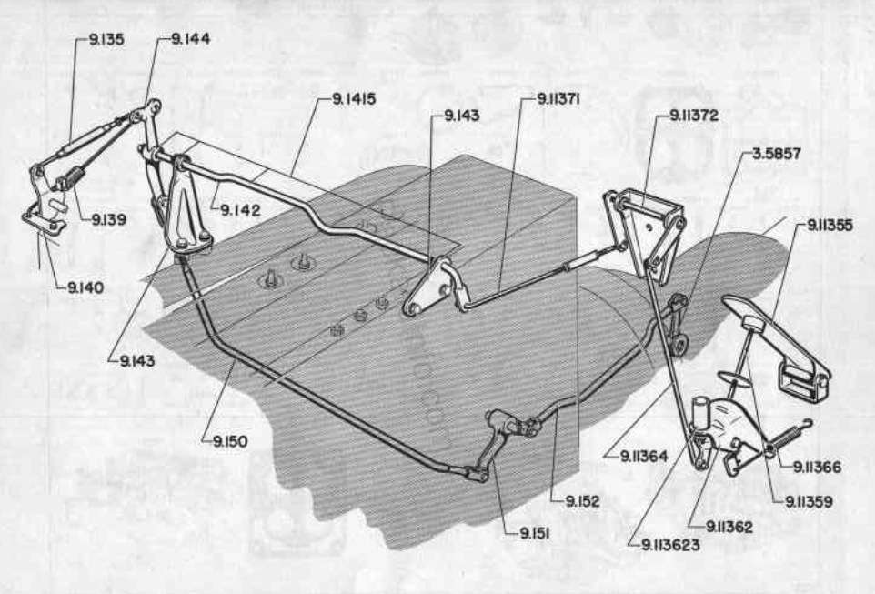
Posted on: 2011/1/29 14:17
|
|||
|
Howard
|
||||
|
||||
|
Re: Temp sending Unit
|
||||
|---|---|---|---|---|
|
Home away from home
|
HEY! Just in time! I just got done setting my TV linkage based on pics another user uploaded...now we know for sure!
The linkage moves as Ross and 51packard suggested, hit the gas and the rod, with arm up, rotates clockwise. It would work if there was a t with a smaller thread male on the T part and female larger threads on the other so i wouldn't have to use a nipple (short coupler). You know pipe thread though, couple turns and it's snug, so there's always threads hanging out of a fitting. If the fittings fit tighter together, wouldn't be an issue.
Posted on: 2011/1/29 17:06
|
|||
|
||||
|
Re: Temp sending Unit
|
||||
|---|---|---|---|---|
|
Home away from home
|
Attached is what i think i'm going to end up going with, and a pic of how bulky the galvanized pipe t setup is.
I couldn't find brass at home depot/lowes, but did at handyman hardware. The bass pieces screwed in more before tightening, and were smaller than their galvanized/black pipe counterparts. I MIGHT have been able to use a 3/8" brass t and the reducing bushing and close nipple like you showed above, but the probe is so long i'd have a coupler and cap at the other end of the T and still end up with a ton of fittings. The probe fits snug inside the 3/8" pipe fittings, and after some cleanup with a drill, inside pipes or nipples too. There are grooves lengthwise along the probe that will make sure antifreeze gets up there, after i bleed it. I'm still not pleased with the looks and wish i would have drilled and tapped it with the motor out, but this will have to work for now. I'll likely get an el cheapo gauge/sender and just lay it in the car for the first 50 miles or so and see what temp is, then hook it up and see what my gauge reads and mark down what "normal" is and keep it in the glove box so i'll know "hot" if i see it. Ok, going back to the store. it's too ugly, going to try nipple and reducing bushing. It's just frustrating because no one place has all the pieces. Attach file: (122.00 KB)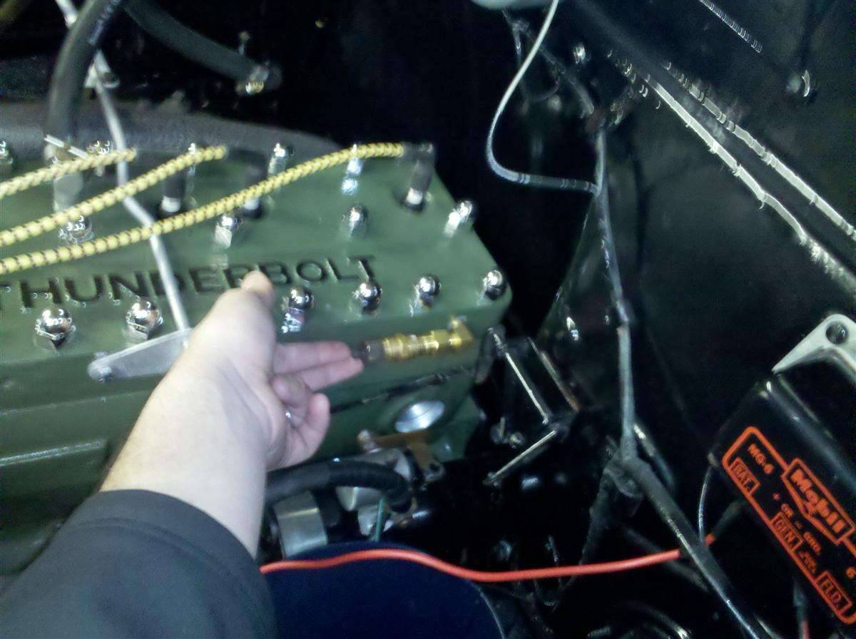 (120.91 KB) (120.91 KB)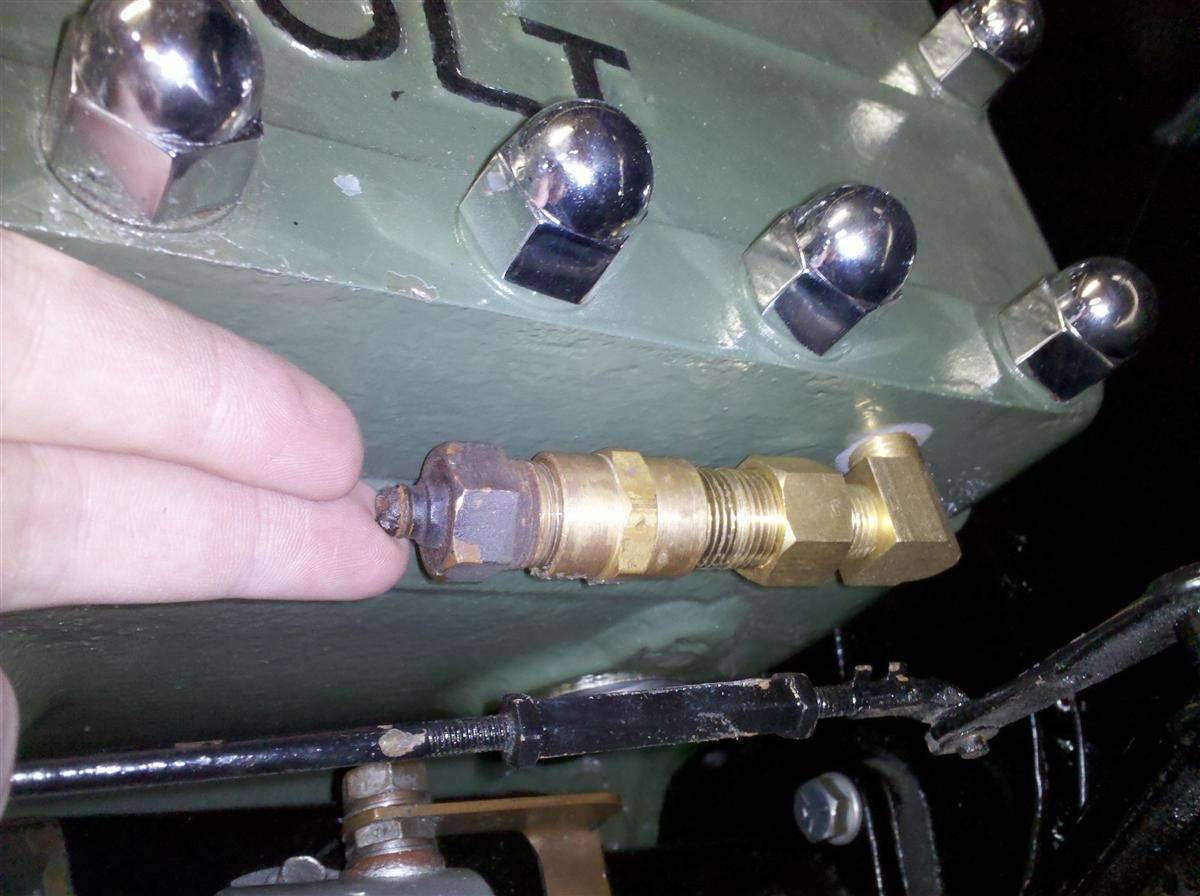 (97.83 KB) (97.83 KB)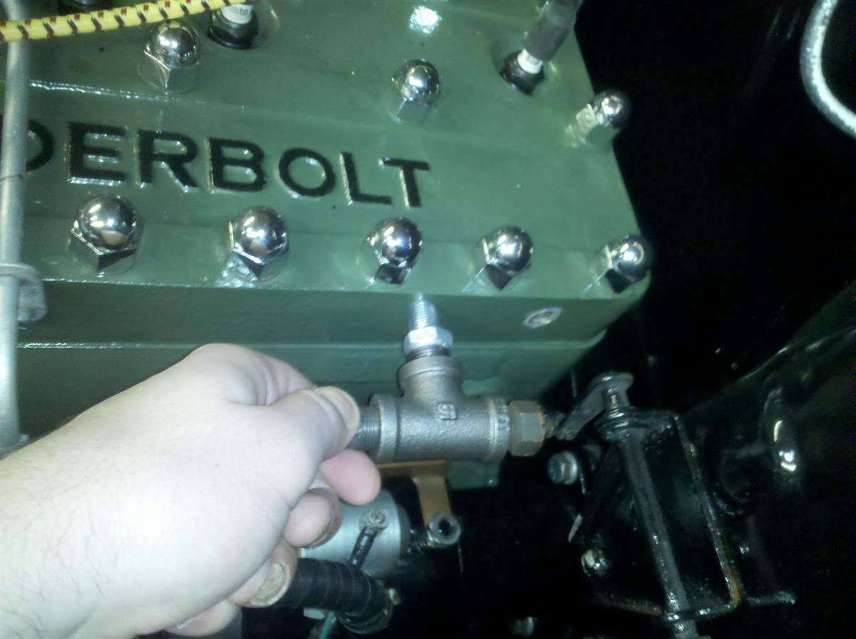
Posted on: 2011/1/30 12:36
|
|||
|
||||
|
Re: Temp sending Unit
|
||||
|---|---|---|---|---|
|
Forum Ambassador
|
Looks good. Nice and compact. The galvanized did turn out larger than I envisioned with that bushing. Really wonder how much water is going to reach sender though. Think its going to be mostly conduction from the block -- but better than nothing.
Posted on: 2011/1/30 13:18
|
|||
|
Howard
|
||||
|
||||


